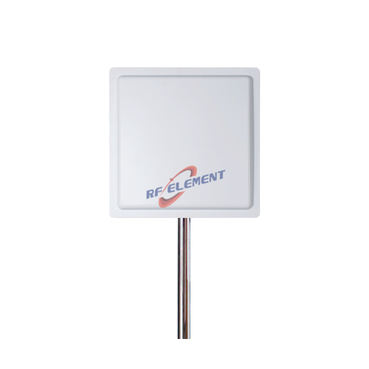
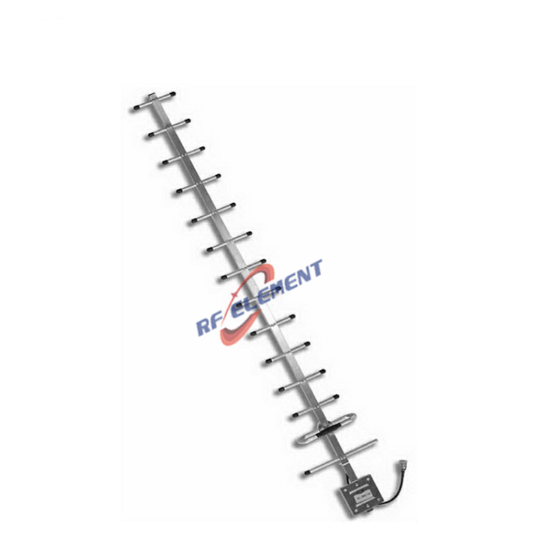
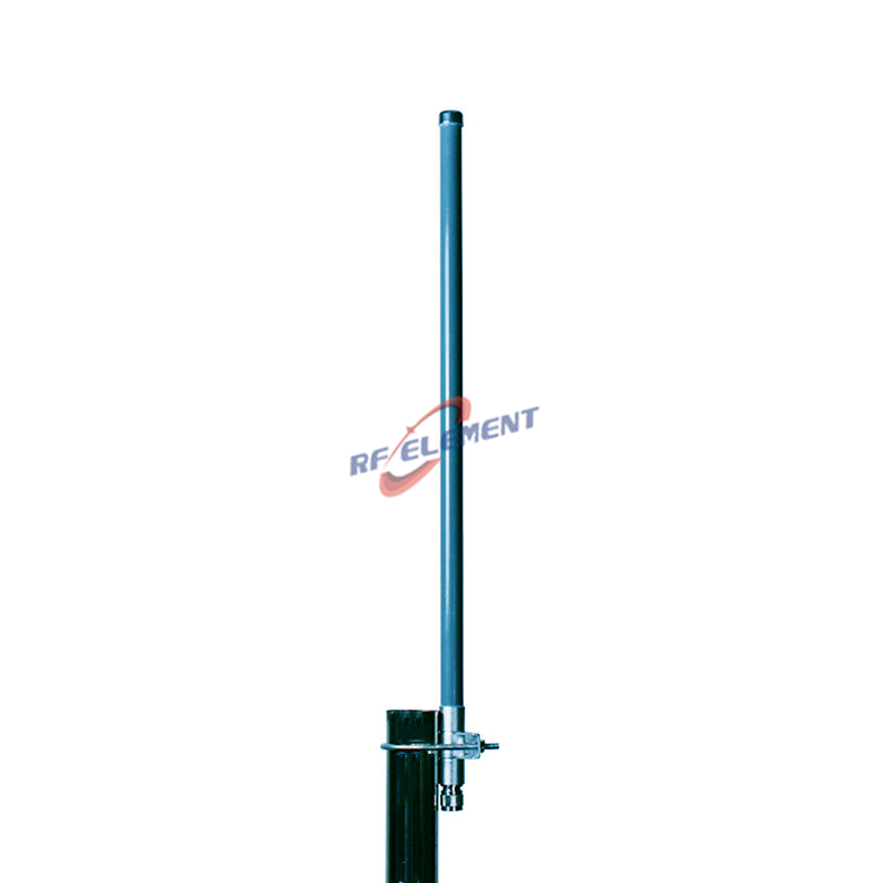
900MHz MIMO Sector Antenna | High Gain Base Station Sector Antenna
900MHz MIMO Base Station Sector Antenna
1, Frequency range: 698-960MHz
2, Gain: 17dBi
3, Polarization: ±45°
4, Half power beam width: H 90°, V 10°
Specifications
This 900MHz MIMO base station sector antenna delivers 17dBi dual-polarized gain across 698-960MHz with a 90 degree horizontal beamwidth and a narrow 10 degree vertical pattern. It was developed for a base station integrator who needed high-gain sector coverage in the low band without the oversized panel that usually comes with it, and it combines ±45 degree polarization with die-cast aluminum elements in a housing that still installs on a standard pole.
Why 17dBi at 900MHz is a size problem
Gain and physical aperture are tied together, and the relationship gets expensive as frequency falls. At 900MHz the free-space wavelength is roughly 33cm, so a 17dBi array needs a longer radiating aperture than a 2GHz panel of the same gain. Push the design with conventional stamped elements and the antenna grows in both length and weight, which raises wind load, demands heavier mounting hardware and complicates tower loading calculations.
The brief was therefore split into two problems: hold 17dBi across the full 698-960MHz span, and keep the mechanical envelope close to what a normal sector install expects. The second constraint shaped the first.
Dual-polarized sector design
We designed the antenna around a ±45 degree dual-polarized MIMO array rather than a single-polarized stack. Two orthogonal slants in the same aperture give the radio two decorrelated data streams, which is what 2x2 MIMO needs in a multipath environment, and it does so without adding a second panel to the sector. For an operator running 4x4 or higher order MIMO, two of these units can be combined per sector.
The radiating elements are die-cast aluminum rather than assembled sheet parts. Casting produces a rigid element with consistent geometry from unit to unit, which matters at 900MHz because small dimensional drift shows up directly as gain loss and pattern distortion. It also removes fasteners and joints that can corrode or generate passive intermodulation over time.
The vertical beamwidth of 10 degrees is deliberately tight. On a tall site it concentrates energy toward the horizon, extends usable range and reduces spill above the horizon, which is where interference with neighbouring cells usually starts. The 90 degree horizontal pattern is the standard building block for a three-sector site covering 360 degrees.
Technical specifications
| Parameter | Value |
|---|---|
| Frequency range | 698-960MHz |
| Gain | 17dBi |
| VSWR | <1.8 |
| Polarization | ±45° dual-polarized |
| Horizontal beamwidth | 90° |
| Vertical beamwidth | 10° |
| Radiating element | Die-cast aluminum |
Gain and beamwidth were confirmed by test and then refined in a second iteration, because the first prototype traded a little gain for pattern width. The released version holds both targets across the band rather than only at the centre frequency.
Sector planning notes
Use three units per site for a 360 degree layout, with the mechanical downtilt set from the sector geometry rather than from a default value. Because the vertical beam is only 10 degrees wide, a small tilt error moves the coverage footprint noticeably; check the pattern against the actual antenna height before fixing the brackets. Keep the two polarization ports on equal-length jumpers so the phase relationship the radio expects is preserved, and torque the connectors to the manufacturer specification to avoid PIM drift after a season of thermal cycling.
In the low band, the Fresnel zone is wide, so sector-to-sector overlap should be planned from the terrain and clutter rather than from the antenna pattern alone. Where a site serves both 900MHz private or cellular traffic and public safety users, the pattern stability across 698-960MHz is what keeps the sector boundary in the same place for every channel.
Customization and ordering
The same platform can be re-cut for a different gain, a different horizontal beamwidth, or a narrower sub-band if the project does not need the full 698-960MHz span. Connector type, mounting brackets, radome colour and OEM packaging are all open to change, and the element geometry can be tuned for a specific operator band plan.
Send the band plan, gain target, beamwidth and quantity to sales@rfelement.com. Samples are typically ready in 3-5 working days and mass production in 15-25 working days.
FAQ — 900MHz MIMO Sector Antenna
What is the 900MHz MIMO Sector Antenna used for?
What frequency band does the 900MHz MIMO Sector Antenna cover?
What are the key specifications of the 900MHz MIMO Sector Antenna?
Can RF element customize the 900MHz MIMO Sector Antenna for my application?
What is the MOQ and lead time for the 900MHz MIMO Sector Antenna?
How do I get a quotation for the 900MHz MIMO Sector Antenna?