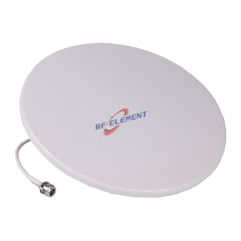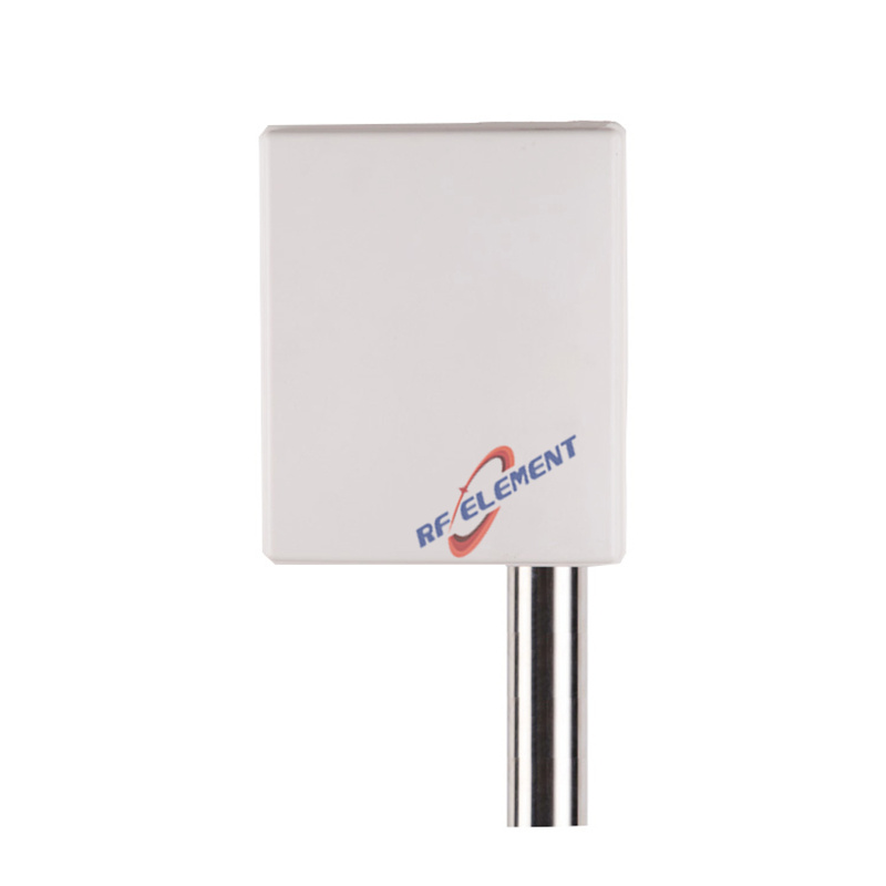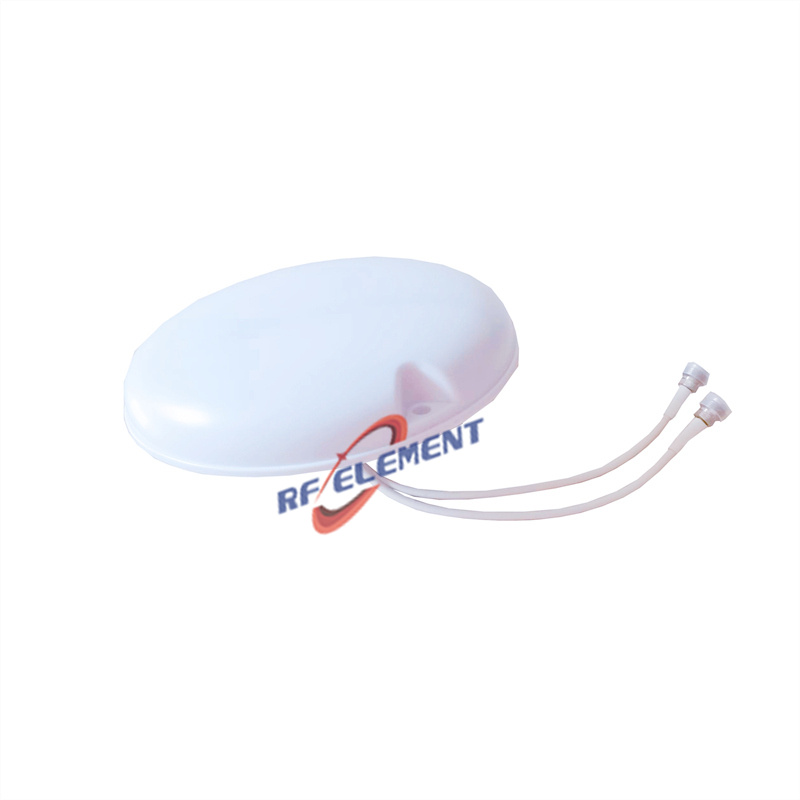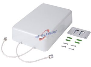


5G IoT Antenna | 4G/5G GPS Puck Antenna for IoT Applications 700-3800MHz
Upgrade your IoT devices with RF element's versatile 5G IoT antenna. This compact puck antenna integrates 4G/5G cellular (700-3800MHz) and GPS into a single, IP65-rated enclosure, making it perfect for fleet management, smart agriculture, asset tracking, and industrial IoT deployments. Its low-profile design ensures easy installation on vehicles or equipment. Get a quote for your IoT project today!
Specifications
A puck antenna that carries 700 to 3800 MHz cellular and GPS in one 80 mm housing is a packaging problem before it is an RF problem. Two radios share one ground plane, two cables leave through the same base, and the two ports look identical from the outside. The numbers that decide whether the installation works are the ground plane under the puck, the cable loss between the puck and the router, and the fact that the 28 dBi in the GPS column is amplifier gain rather than antenna gain. This page takes those three items in turn, then covers the port swap that causes most of the returns on this type of part.
The 28 dBi in the GPS column belongs to the amplifier
A passive GPS patch of this size produces about 3 to 5 dBi at 1575.42 MHz, and no amount of packaging changes that. The 28 dBi in the second column is the gain of the active module that sits under the patch, and it is quoted at the output of the antenna rather than at the radiating element. The figure is real, but it describes a different thing from the 3 dBi in the cellular column, and reading the two as comparable numbers is the first mistake a spec sheet invites.
What preserves a GPS signal is not the gain of that amplifier but its noise figure and its position in the chain. The module has to be at the antenna, ahead of the cable, because every decibel of cable loss after the amplifier adds directly to the system noise figure. The gain then only has to be large enough to overcome the cable and the receiver front end. If the amplifier is in the receiver instead, 5 m of RG174 at 1.575 GHz, which is about 3 dB, removes half the signal before it is amplified and no later stage can recover it.
Three dBi from an 80 mm puck is a ground plane number
At 700 MHz the free space wavelength is 429 mm, so the 80 mm body is 0.19 wavelengths across. A radiator that small on its own is close to 0 dBi. The 3 dBi in the table arrives when the puck sits on a metal surface large enough to act as a counterpoise, which is why the same antenna reads differently on a vehicle roof and on a plastic enclosure.
The rule of thumb is a quarter wavelength at the lowest frequency, which is 107 mm at 700 MHz. A vehicle roof, a metal cabinet or a steel mast clears that easily. A fibreglass boat, a wooden shed or a plastic control box does not, and the result is not a small loss: 3 to 6 dB of gain disappears and the match moves, because the ground plane is part of the resonator. Where no metal exists, a ground plane kit or a metal plate of at least 200 mm across restores most of the performance, and it is cheaper than discovering the problem after the units are installed.
| Frequency Sub-Range | 700-3800 MHz | 1575.42±5 MHz |
| Polarization | Vertical | |
| Gain(dBi) | ≥3 | ≥28 |
| Impedance | 50Ω | |
| VSWR | ≤3.00 | ≤2.0 |
| Maximum Power | 50W | |
| Connector Type | 2 Port, SMA Male | |
| Antenna Dimension(mm) | Φ 80*27 | |
| Net Weight | 0.2 kg | |
| Operating Temperature | -40° to +60° C (-67° to +140° F) | |
| Radome Material | ABS | |
| Radome Color | Black | |
| Mounting Options | Fasteners and screws included for pole mounting | |
VSWR 3.0 across a 5.4 to 1 band is a choice, not a defect
The cellular port covers 700 to 3800 MHz, a ratio of 5.4 to 1, from a body 80 mm across and 27 mm high. Holding a match better than 1.5 to 1 across that range would require a much larger structure, so the design accepts a worst case of 3.0. That is a reflection coefficient of 0.5, a return loss of 6 dB and a mismatch loss of 1.25 dB.
Whether 1.25 dB matters depends on the link. For a tracker or a sensor uploading at 20 to 23 dBm into a network that is limited by the uplink, 1.25 dB is a fair trade for a part that fits on an 80 mm footprint. For a router running high order modulation at the edge of a cell, where 1 dB is worth a modulation step, a larger antenna with a better match is the right answer. The number to carry into a link budget is the worst case at the band edges, not the typical value in the middle.
Two identical SMA male ports: the most common field error
Both ports are SMA male, both leave the same base, and nothing on the housing forces the installer to connect them the right way round. Swapping them is common, and the consequences are not symmetrical. The GPS port carries a DC bias, typically 3.3 or 5 V, from the receiver up to the amplifier. Feeding that bias into the cellular port is usually harmless, but feeding the output of a 5 W cellular radio into the GPS amplifier destroys it, and the failure appears as a receiver that no longer sees satellites rather than as a radio fault.
Two habits remove the risk. Label both ends of both cables before they go up the mast, using different colours, and check the ports with a multimeter before the first power up: the GPS port shows the DC path to the amplifier, the cellular port does not. A measurement takes a minute and is more reliable than a part number printed in 6 point type on a black radome.
Cable loss at 3.8 GHz and the mounting details
Cable loss is the item that quietly eats the cellular gain. At 3.8 GHz, thin cables of the RG174 class lose between 0.8 and 1.2 dB per metre, so a 3 m run costs 2.4 to 3.6 dB, more than the antenna produces. A 5 m run of the same cable can cost 6 dB, which is the difference between a usable and an unusable uplink at the cell edge. Where the router sits more than 2 m from the puck, step up to a larger coax or shorten the run; the GPS side is far more tolerant because the amplifier is already at the antenna.
The mechanical package is 0.2 kg in a body 80 mm across and 27 mm high, sealed to IP65, with an operating range from minus 40 to plus 60 degrees Celsius. That lower limit is worth noting because it is 15 degrees warmer than the rest of this catalogue, and it matters for equipment mounted on a cold store roof or in a winter climate. Fasteners for pole mounting are included, and the connector threads should be sealed with self amalgamating tape rather than silicone, which traps water instead of excluding it.
For a network that is mostly short range and mostly battery powered, a LoRa omni antenna 868 and 915 MHz is a better match than a wideband puck. Where the installation is a fixed UHF base rather than a moving asset, a detachable UHF omni antenna trades the wide band for 3 dBi of real gain in one band. To compare the two shapes against a specific radio, the antenna selector tool filters by band, gain and mounting type.
Send the radio model, the cable length and a photo of the mounting surface to sales@rfelement.com, and we will confirm the ground plane requirement and the port assignment before the order is placed.
FAQ — 5G IoT Antenna
What is the 5G IoT Antenna used for?
What frequency band does the 5G IoT Antenna cover?
What are the key specifications of the 5G IoT Antenna?
Can RF element customize the 5G IoT Antenna for my application?
What is the MOQ and lead time for the 5G IoT Antenna?
How do I get a quotation for the 5G IoT Antenna?