

Full Wireless Antenna Portfolio
Browse the Catalogue by Antenna Family
Every model in this catalogue belongs to one of seven families. The family is decided by the radio you already own, not by the antenna: fix the band, then the mounting position, and the list usually narrows to two or three part numbers.
| Family | Frequency | Where it is used | Catalogue pages |
|---|---|---|---|
| 5G NR / MIMO | 617–4200 MHz (n41, n77, n78); n79 at 4400–5000 MHz is built as a separate design | Rooftop sector panel, indoor ceiling, small cell, outdoor CPE | 5G antennas, cellular antennas |
| 4G LTE / 3G / GSM | 698–2700 MHz, covering LTE bands 1, 3, 5, 7, 8, 20, 28 and TDD 38/40/41 | Macro sector, in-building coverage, router and CPE | 4G LTE antennas, 3G / GSM antennas, Base Station Panel Antenna |
| Wi-Fi | 2.4–2.5 GHz, 5.15–5.85 GHz, or one dual-band radiator | Access point omni, sector for point-to-multipoint, CPE yagi | Wi-Fi antennas, 2.4 GHz, 5 GHz, dual-band |
| LoRa / sub-GHz ISM | 433, 450–470, 470–510, 860–930 MHz, matched per region | Sensor node, gateway, short backhaul between poles | LoRa antennas, 868 MHz, 915 MHz, 433 MHz |
| RFID / UHF | 865–868 MHz in Europe, 902–928 MHz in North America | Portal and dock-door readers, conveyor read points | RFID antenna guide, 915 MHz RFID panel |
| Low-PIM / DAS | 698–2700 or 698–3800 MHz, rated −150 dBc at 2×20 W | Indoor DAS, stadium, tunnel, venue ceiling | Low-PIM antennas, DAS in-building |
| GNSS / GPS | 1575.42 MHz L1; L2 and L5 on multi-band receivers | Telematics puck, fleet roof unit, timing antenna | 4G / 5G / GPS puck, fleet antennas |
The catalogue is only the standard range. If a band edge, a footprint or a connector is not in the list, the same housing is usually modified rather than replaced — see the custom build notes below.
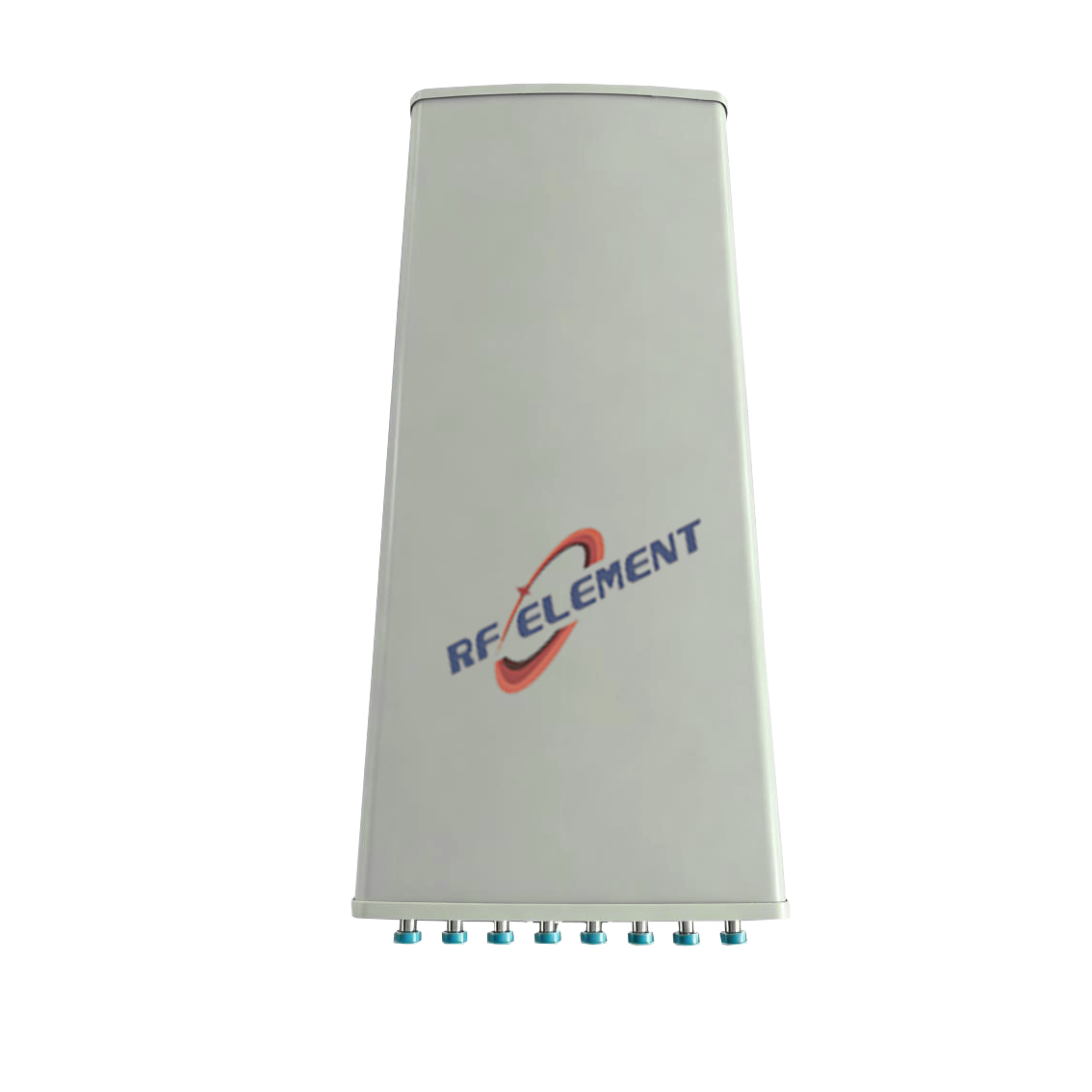
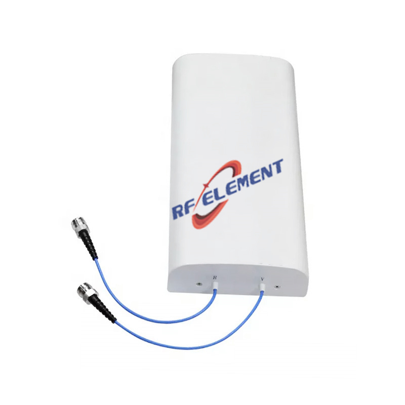
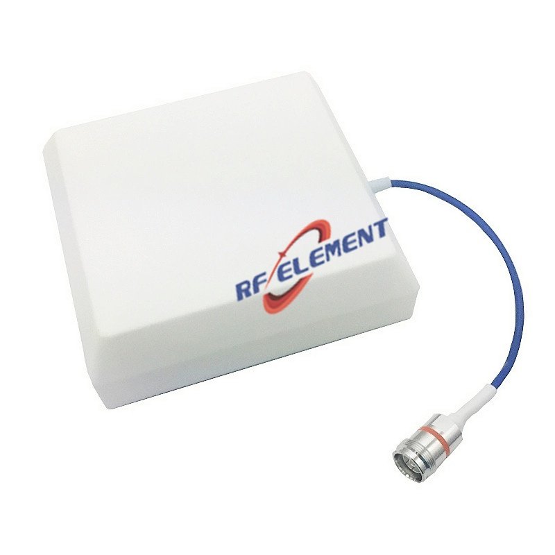



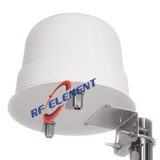
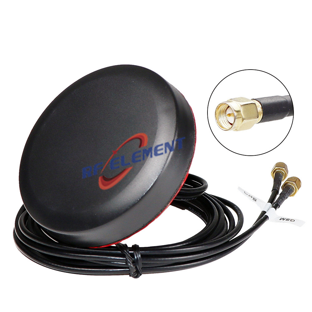
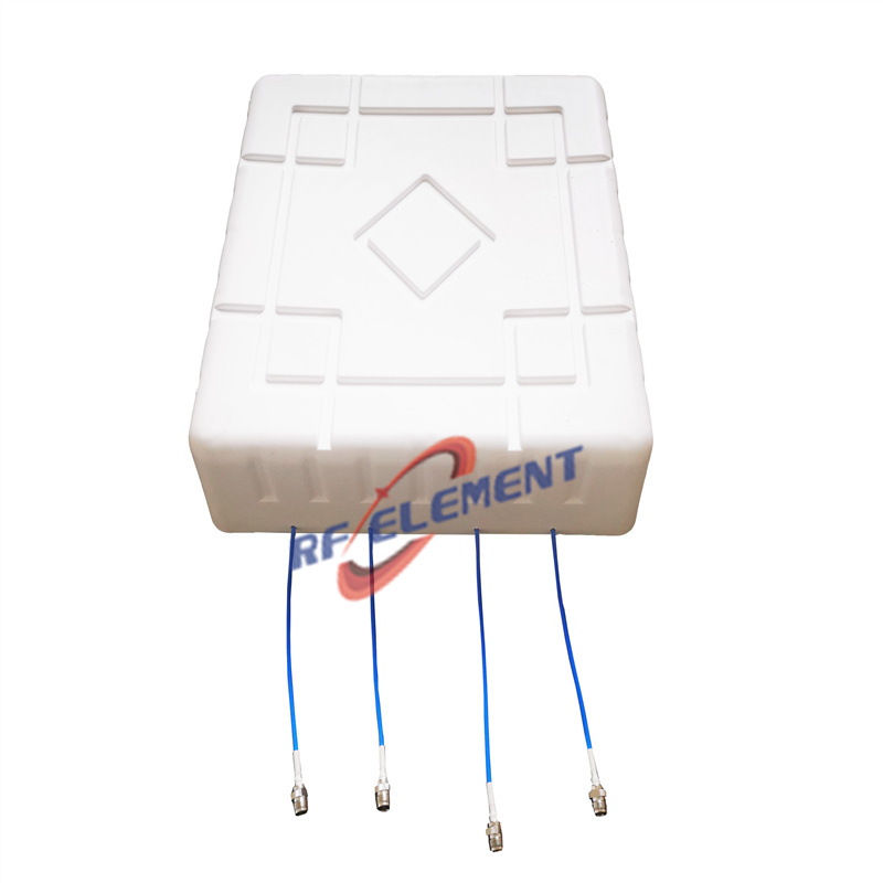
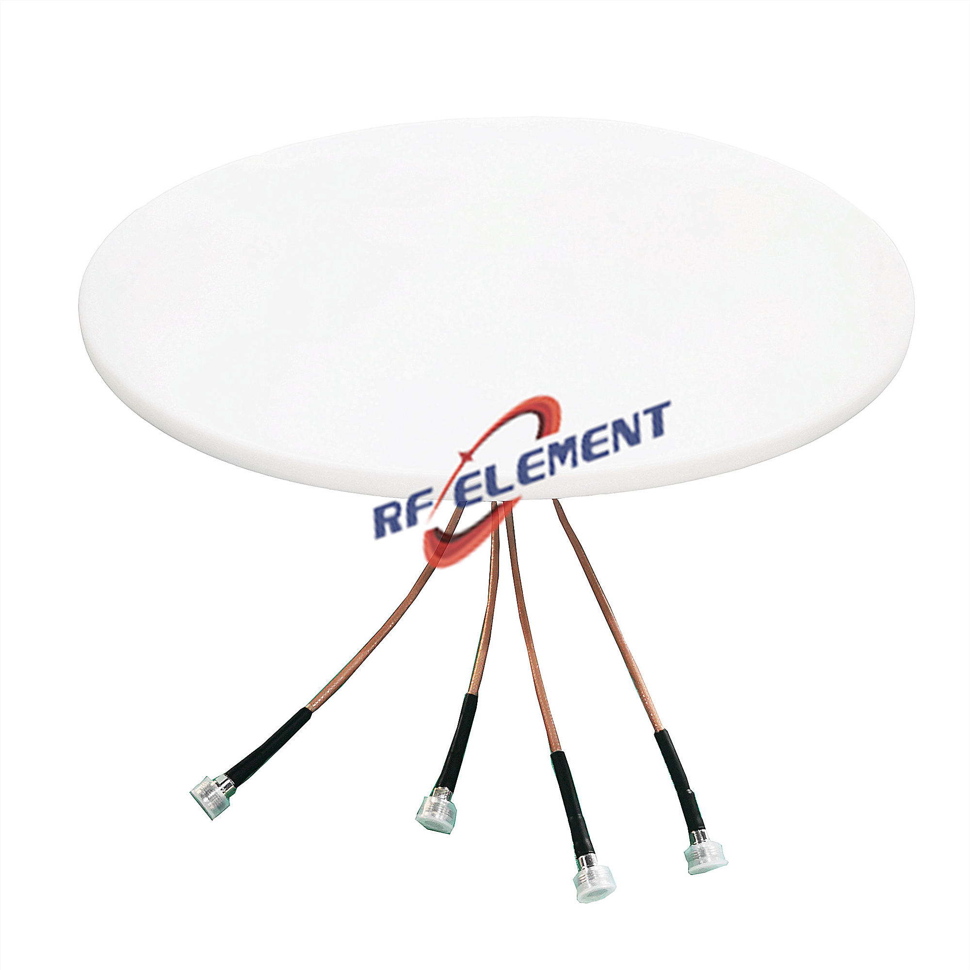
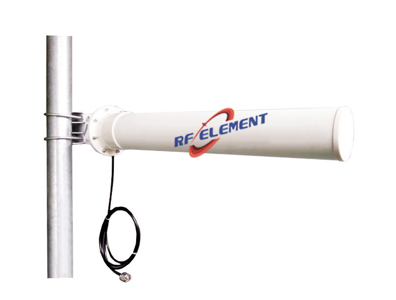
Four Steps from Catalogue Model to Production Part Number
The datasheet headline is gain in dBi. What decides whether a link closes is the behaviour at the band edges, the pattern where the antenna is actually mounted, and the loss between the antenna and the radio.
| Step | What to fix first | Why it decides the model | Go deeper |
|---|---|---|---|
| 1. Band edges | Return loss or VSWR across the whole band, not at the centre frequency. Where uplink and downlink are split, check both halves separately. | LTE Band 31 runs 452.5–457.5 MHz uplink and 462.5–467.5 MHz downlink. A 450–460 MHz antenna covers the uplink and stops short of the downlink, however good its gain looks. | 450 MHz antennas |
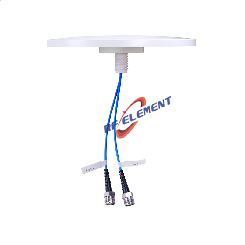
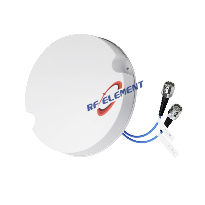
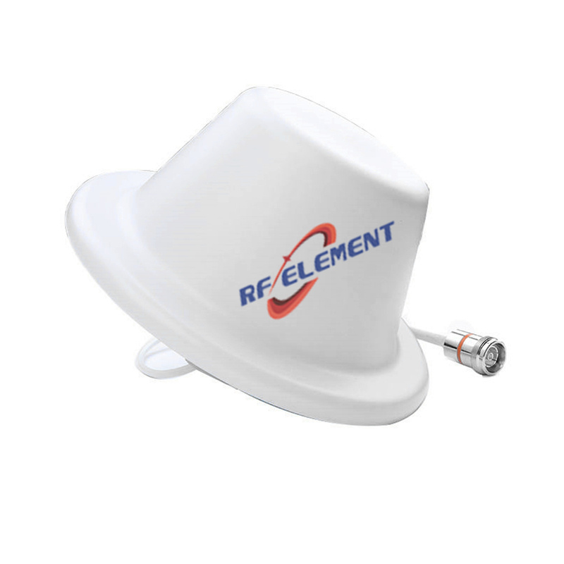
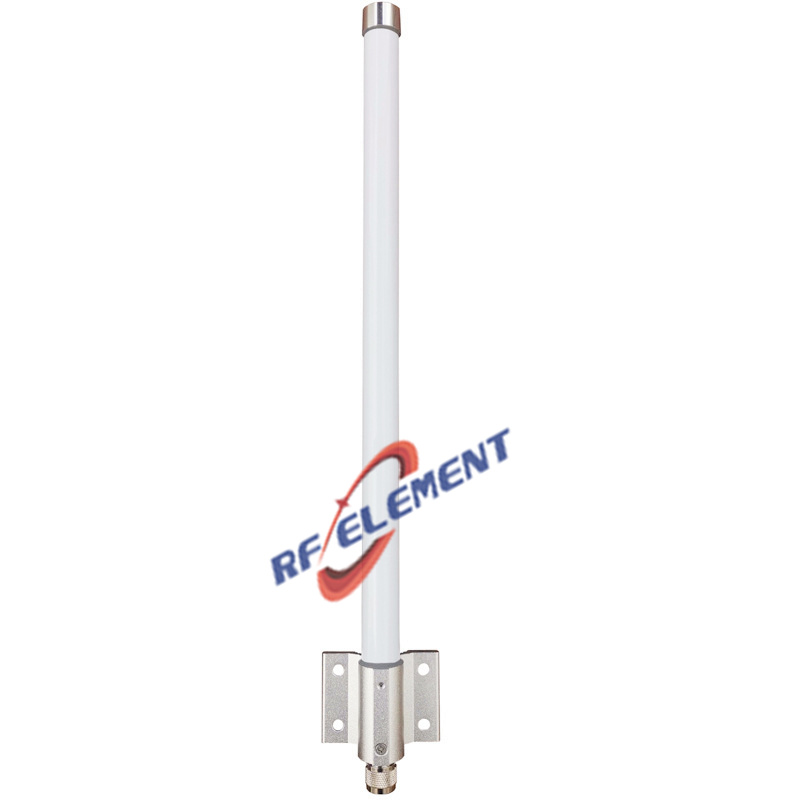
| 2. Mounting position | Panel for a sector, omni for 360° coverage, ceiling for indoor distribution, yagi for a point-to-point hop, puck for a roof. | The mount sets the pattern far more than the gain figure does. A high-gain panel aimed at the wrong bearing performs worse than a modest omni that covers the site. | 5G, LoRa, Wi-Fi |
| 3. Gain and beamwidth | Choose the coverage angle before the gain. Horizontal and vertical beamwidth together fix the directivity: D ≈ 10 log10(41253 / (H × V)). | A 65° sector concentrates power into a narrower arc than a 90° sector of the same family. In a dense site the narrower beam raises interference; on a long rural hop it is the reason the link closes. | 65° vs 90° beamwidth |
| 4. Connector, cable, environment | Connector type, cable length and route, then the enclosure rating for the site: IP67, UV-stable radome, −40 to +85 °C. | Cable loss can erase the gain you paid for: 5 m of RG58 loses about 3 dB at 2.6 GHz, which is half the power, before the signal reaches the radio. | Low-PIM antennas |
When two models look identical on paper, ask for the VSWR sweep at both band edges and a pattern cut in the plane that matters for the site. Those two documents separate a catalogue part that works from one that only measures well at 1 GHz in a lab.
Standard Model or Custom Build?
Most projects start from a catalogue model and change one or two variables. The table below shows what stays fixed and what we rebuild, so you can tell from the first reply whether a standard part is enough.
| Aspect | Standard catalogue model | Custom / OEM-ODM build |
|---|---|---|
| Frequency | Published bands and connectors, shipped from stock designs | Any band inside our UHF–13 GHz design range, including split uplink and downlink windows |
| Housing and mounting | Existing radome, base and bracket | New radome, base, colour and logo. Die-casting, plastic injection, CNC machining and laser processing are in-house, so a prototype does not wait on a subcontractor |
| Connector and cable | Standard N, SMA or 4.3-10 options | Specified connector and cable assembly, sealed and strain-relieved at the base |
| Testing | Sample VSWR sweep | VSWR sweep, pattern cut and PIM at −150 dBc at 2×20 W in our own anechoic chamber, with the data shipped alongside the units |
| Samples and volume | Samples in 3–5 days for catalogue models | Prototype after drawing approval, then production runs with packaging and labelling to your specification |
What to Send with an RFQ
- The band plan: uplink and downlink frequencies, and whether the radio runs 2×2 or 4×4 MIMO.
- Where the antenna is mounted and the space available: roof, pole, ceiling, vehicle or enclosure.
- Coverage requirement in words or degrees, plus the gain you expect, so the beamwidth can be checked against it.
- Connector type, cable length and the route the cable takes to the radio.
- Quantity for the pilot and for the production run, and the date the units have to be on site.
Send those five points and you get a part number, a drawing and a price in one reply — engineering answers within 1–2 working hours. Two shortcuts: the antenna selector narrows the catalogue by band, mounting and gain in three filters, and the project case studies show what a custom build looks like from drawing to production. To start a project directly, use the contact form.
