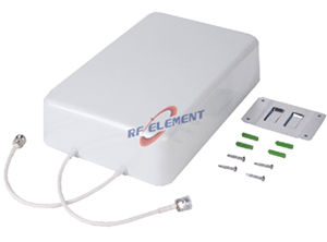

5G Camouflage Antenna | Dual Polarity Spotlight Antenna,800-3800MHz
Enhance your outdoor wireless network with RF element's Dual Polarity Beautification Spotlight Antenna. Designed for seamless 4G/LTE and 5G integration, this low-profile, high-gain antenna operates across 800-3800MHz with a 13dBi gain. Its aesthetic radome blends with the environment, making it perfect for DAS applications. Contact us for a tailored solution.
Specifications
A two-port directional panel built into a spotlight housing so that it can be mounted on street furniture, lamp posts and building facades without a planning objection. The electrical design covers 800-3800 MHz in three sub-ranges with 9 dBi at 806-960 MHz, 11 dBi at 1710-2700 MHz and 13 dBi at 3300-3800 MHz. The reflector is 430 x 420 mm, 135 mm deep, and the complete unit weighs 4 kg.
The housing is the specification
In a residential street, a heritage zone or a public square, the objection to a cellular antenna is rarely electrical. A black UPVC housing shaped like a spotlight can be mounted on a lighting column that already exists, at a height and orientation that the local authority has already accepted for street furniture. That is the whole purpose of this product, and it is why the mechanical drawing matters as much as the gain table.
The trade is weight and depth. At 4 kg and 135 mm, the unit needs a mounting that can carry it and a cable entry that stays watertight on a vertical column. Confirm the column capacity and the fixing detail before the electrical design is frozen.
Narrow beams for a street sector
The horizontal beamwidth is 35 degrees at 806-960 MHz, 28 degrees at 1710-2700 MHz and 22 degrees at 3300-3800 MHz. These are sector figures rather than coverage figures: the unit is intended to illuminate a length of street or a face of a building, not a whole junction. Front-to-back ratio of at least 20 dB in every sub-range is what allows two units to be mounted on opposite sides of a column without coupling into each other.
Because the beam is narrow, aiming accuracy matters. A 22 degree horizontal beam at 3.5 GHz covers about 39 m of width at 100 m, so a five degree aiming error moves the coverage edge by roughly 9 m. Use the mechanical bracket to set the azimuth against a map rather than by eye.
| Frequency Range | 800-3800MHz | ||
| Frequency Sub-Range(Mhz) | 806-960 | 1710-2700 | 3300-3800 |
| Polarization | ±45° | ||
| Gain(dBi) | 9±1 | 11±1 | 13±1 |
| Horizontal Beam width | 35±5° | 28±5° | 22±5° |
| Vertical Beam width | 65±5° | 55±5° | 40±5° |
| Impedance | 50Ω | ||
| VSWR | ≤1.8 | ||
| 3rd Order for 2×2W Carriers | -150 dBc | ||
| Front-to-Back Ratio | ≥ 20dB | ||
| Maximum Power | 100 W | ||
| Connector Type | 2 Port, 4.3-10 Female or N-Type Female | ||
| Length | 430 mm | ||
| Width | 420 mm | ||
| Depth | 135 mm | ||
| Net Weight | 4 kg | ||
| Operating Temperature | -55° to +60° C (-67° to +140° F) | ||
| Radome Material | UPVC | ||
| Radome Color | Black | ||
| Mounting Options | Fasteners and screws included for wall mounting | ||
Reading the PIM condition
The table gives third order PIM as -150 dBc under 2 x 2 W carriers. That is a different test condition from the -153 dBc at 2 x 20 W quoted on the low PIM panels in this range, and the two numbers cannot be compared directly. A 10 dB reduction in carrier power typically improves the measured product by a similar order, so the -150 dBc figure here is not evidence of a better antenna than a -153 dBc part; it is a lighter test.
For a single operator street deployment at moderate power this is adequate. For a shared DAS with two or more carriers combined at the port, ask for the PIM figure at the carrier power you intend to run and compare like with like.
Band coverage and the 800 MHz edge
The lower edge is 800 MHz, so this antenna does not cover the 700 MHz band or the 600 MHz band. That is a consequence of the housing size: a spotlight of this diameter cannot hold a match at 700 MHz without losing gain in the upper bands. If the deployment includes 700 MHz, a conventional panel with a 698 MHz lower edge is the correct part, and the camouflage advantage has to be given up or solved with a different enclosure.
Maximum power is 100 W, which is high for a unit of this size and reflects the metal reflector behind the radiating elements. The 50 ohm impedance and VSWR of 1.8 or better across all three sub-ranges are consistent with a designed reflector rather than a printed dipole in a plastic box.
Ordering
Two 4.3-10 female or N-Type female ports, black UPVC radome and wall mounting hardware are standard. Samples in 3-5 days, production in 15-25 days.
Where appearance is not a constraint, the 698-3800 MHz low PIM panel delivers comparable mid-band gain at 0.4 kg and covers the 700 MHz band. For rooftop and mast positions, the outdoor 2x2 MIMO panel covers 698-4200 MHz with pole clamps.
Send the mounting column type, the band plan and the sector azimuth. If the site includes 700 MHz, say so first, because that single answer rules this housing out before any other specification is discussed.
FAQ — 5G Camouflage Antenna
What is the 5G Camouflage Antenna used for?
What frequency band does the 5G Camouflage Antenna cover?
What are the key specifications of the 5G Camouflage Antenna?
Can RF element customize the 5G Camouflage Antenna for my application?
What is the MOQ and lead time for the 5G Camouflage Antenna?
How do I get a quotation for the 5G Camouflage Antenna?