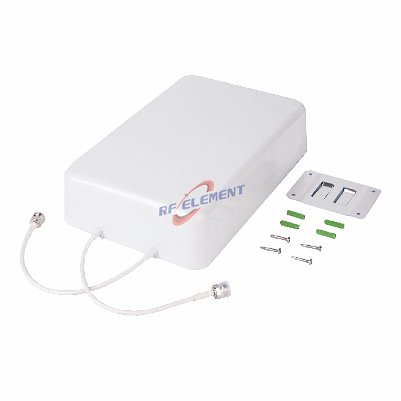
High-Performance 5G Outdoor Antenna | 5G 2x2 MIMO Panel Antenna 698-4200MHz
Specifications
A pole-mounted two-port panel for outdoor coverage where the antenna has to survive on a mast rather than sit on a wall. Coverage runs from 698 to 4200 MHz across six sub-ranges, with a 1350-1550 MHz window that most outdoor panels in this class leave out. Gain is 5 dBi at the bottom edge, peaks at 8 dBi at 1710-2700 MHz and returns to 5 dBi at 3800-4200 MHz, from a 310 x 230 x 73 mm housing weighing 1.0 kg.
What the L-band row buys
The 1350-1550 MHz row is the reason this panel appears in projects that a plain cellular panel cannot serve. That window covers L-band satellite downlinks and the distribution side of indoor GNSS repeaters, which are increasingly specified alongside cellular coverage in airports, data centres and hospitals where timing depends on a satellite reference.
Using one antenna for both services means one mounting position, one cable bundle and one weatherproofing detail on the mast. Where the timing system is added later, the port and the pattern are already there. Check the 1350-1550 gain figure against the link budget of the repeater rather than assuming the mid-band 8 dBi applies.
Isolation that supports dual polarisation
Port to port isolation is 20 dB in the three lower sub-ranges and 25 dB at 3300-4200 MHz. That is 8 to 13 dB better than the four-port plate antenna in the same range, and it is what makes the two ports usable as an independent 2x2 MIMO pair on a pole where the two branches run through separate coax feeders.
On a long feeder run the isolation at the antenna is only part of the budget. Add the feeder loss difference between the two branches and the connector quality at each end; a 1 dB imbalance between branches costs more MIMO performance than a 5 dB change in antenna isolation.
| Frequency Range | 698-4200MHz | |||||
| Frequency Sub-Range(Mhz) | 698-806 | 806-960 | 1350-1550 | 1710-2700 | 3300-3800 | 3800-4200 |
| Polarization | ±45° | |||||
| Gain(dBi) | 5±0.5 | 6.5±0.5 | 6±0.5 | 8±0.5 | 6±0.5 | 5±0.5 |
| Horizontal Beam width | 80±10° | 80±10° | 70±10° | 70±10° | 60±10° | 60±10° |
| Vertical Beam width | 50±10° | 50±10° | 40±10° | 35±10° | 40±10° | 40±10° |
| Impedance | 50Ω | |||||
| VSWR | ≤ 1.8 | ≤ 1.8 | ≤ 1.6 | ≤1.6 | ≤1.8 | ≤2.0 |
| 3rd Order for 2×20 W Carriers | -153 dBc | |||||
| Front-to-Back Ratio | ≥ 10dB | ≥ 10dB | ≥ 10dB | ≥ 15dB | ≥ 15dB | ≥ 15dB |
| Isolation | ≥ 20dB | ≥ 20dB | ≥ 20dB | ≥ 25dB | ≥ 25dB | ≥ 25dB |
| Maximum Power | 50 W | |||||
| Connector Type | 2 Port, 4.3-10 Female or N-Type Female | |||||
| Length | 310 mm | |||||
| Width | 230 mm | |||||
| Depth | 73 mm | |||||
| Net Weight | 1.0 kg | |||||
| Operating Temperature | -55° to +60° C (-67° to +140° F) | |||||
| Radome Material | Plastic ABS | |||||
| Radome Color | White | |||||
| Mounting Options | Pole Mounting | |||||
Front-to-back and co-siting
The front-to-back ratio is 10 dB in the low and middle sub-ranges and 15 dB at 3300-4200 MHz. On a shared mast this figure decides how much energy from one sector reaches the antenna of another facing the opposite direction. Ten decibels in the low band is modest, so two panels mounted back to back on the same pole should be separated vertically by at least one metre rather than mounted at the same height.
Where the mast carries several operators, keep the panel boresight at least 30 degrees away from any other antenna aperture at the same height. Mechanical tilt is more effective than electrical tilt for this purpose because it does not change the pattern shape.
Weight, depth and weather
At 1.0 kg and 73 mm deep, the panel mounts on a pole with standard clamps and adds little wind load. The depth matters on a slim pole where the antenna and the radio unit are stacked: 73 mm plus the radio heatsink clearance is usually within the pole diameter, so the assembly stays inside the structural envelope.
The radome is white ABS. On a coastal site, specify the mounting hardware in stainless steel and seal the connector with self-amalgamating tape rather than PVC tape, which degrades in ultraviolet light within a season.
Ordering
Two 4.3-10 female or N-Type female ports, radome colour and packing quantity are confirmed at order. Samples in 3-5 days, production in 15-25 days.
If the installation is indoors and wall mounted, the indoor wall mount version uses the same 310 x 230 mm plate with a wall bracket instead of pole clamps. Where the requirement is a ceiling position rather than a mast, the DAS in-building antenna range groups the ceiling units by void depth.
Tell us the mast height, the feeder length and whether the L-band window is in scope. The last answer decides whether this panel or a plain 698-3800 MHz unit is the correct part.
FAQ — High-Performance 5G Outdoor Antenna
What is the High-Performance 5G Outdoor Antenna used for?
What frequency band does the High-Performance 5G Outdoor Antenna cover?
What are the key specifications of the High-Performance 5G Outdoor Antenna?
Can RF element customize the High-Performance 5G Outdoor Antenna for my application?
What is the MOQ and lead time for the High-Performance 5G Outdoor Antenna?
How do I get a quotation for the High-Performance 5G Outdoor Antenna?