5G Signal Booster Antenna | Panel Antenna for 4G/5G Networks | 698-4200MHz
Specifications
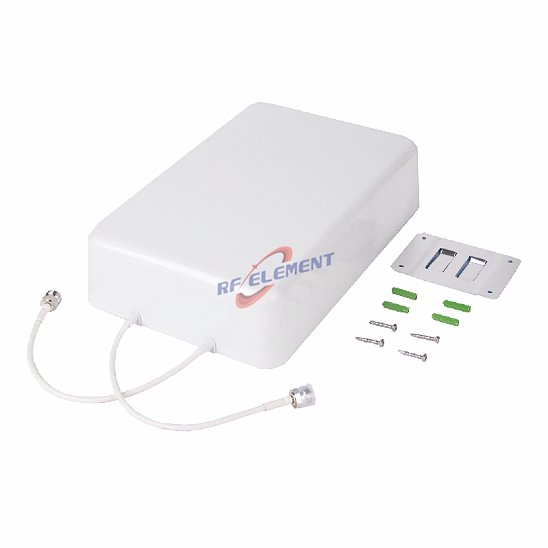
A 698-4200 MHz single-port panel intended for signal booster and repeater installations rather than for a high power DAS head end. Five sub-ranges are specified, with 5 dBi at 698-806 MHz rising to 7 dBi at 1710-2700 MHz and settling at 6 dBi in the two upper sub-ranges. The 165 x 155 x 50 mm housing weighs 0.4 kg and terminates in one 4.3-10 female or N-Type female port.
Donor and server are two different jobs
A booster installation needs two antennas with opposite requirements. The donor antenna points at the donor cell and needs directivity plus front-to-back ratio, because it is receiving a weak signal in the presence of stronger ones from other directions. The server antenna distributes the amplified signal inside the building and needs a wide, even pattern with no hot spot close to the unit.
This panel is used for both roles in low to medium power systems. Its 90 degree horizontal beam at 698-960 MHz and 75 degrees at 1710-2700 MHz give the server role enough spread for a single room or a short corridor, while the 10 to 15 dB front-to-back ratio is enough for a donor position that is not surrounded by strong interferers. Where the donor signal is weak and directional, a Yagi is the better tool.
The VSWR figure at the top of the band
The table shows VSWR at or below 1.8 in the low band, 1.5 to 1.6 in the middle, and 2.0 at 3800-4200 MHz. A VSWR of 2.0 corresponds to a return loss of about 9.5 dB, which means roughly a tenth of the forward power is reflected. For a booster running a few watts that is not a problem; for a 20 W per carrier DAS it is, and that is why this panel is specified for booster duty.
If the band plan stops at 3800 MHz, the 2.0 figure never applies and the antenna behaves like a 1.6 VSWR part across its working range. Confirm the top of the band before comparing this panel with a low PIM unit on price.
| Frequency Range | 698-4200MHz | ||||
| Frequency Sub-Range(Mhz) | 698-806 | 806-960 | 1710-2700 | 3300-3800 | 3800-4200 |
| Polarization | Vertical | ||||
| Gain(dBi) | 5±0.5 | 6±0.5 | 7±0.5 | 6±0.5 | 6±0.5 |
| Horizontal Beam width | 90±10° | 90±10° | 75±20° | 50±20° | 50±20° |
| Vertical Beam width | 90±10° | 85±10° | 65±20° | 40±20° | 40±20° |
| Impedance | 50Ω | ||||
| VSWR | ≤ 1.8 | ≤ 1.5 | ≤ 1.6 | ≤1.6 | ≤2.0 |
| 3rd Order for 2×20 W Carriers | -153 dBc | ||||
| Front-to-Back Ratio | ≥ 10dB | ≥ 10dB | ≥ 15dB | ≥ 15dB | ≥ 10dB |
| Maximum Power | 50 W | ||||
| Connector Type | 1 Port, 4.3-10 Female or N-Type Female | ||||
| Length | 165 mm | ||||
| Width | 155 mm | ||||
| Depth | 50 mm | ||||
| Net Weight | 0.4 kg | ||||
| Operating Temperature | -55° to +60° C (-67° to +140° F) | ||||
| Radome Material | Plastic ABS | ||||
| Radome Color | White | ||||
| Mounting Options | Fasteners and screws included for wall mounting | ||||
Coverage in the low band
The 90 degree horizontal and 90 degree vertical beam at 698-806 MHz makes the pattern close to a hemisphere in front of the panel. For a booster serving an open plan room, that is exactly what is wanted: a broad wash of signal with no narrow lobe that has to be aimed. The trade is that 5 dBi does not project far through dense construction, and a second unit is usually cheaper than a higher gain antenna when the space is divided by masonry walls.
Above 3.3 GHz the horizontal beam narrows to 50 degrees and the vertical beam to 40 degrees, so the same panel becomes a directional element for a 5G repeater covering a specific zone rather than a whole floor.
Installation practice
Fasteners and screws for wall mounting are included. Keep 200 mm of clearance in front of the radome; a booster antenna mounted tight under a metal ceiling or against a steel column will show a VSWR rise that the installer will see as a fault in the repeater rather than in the antenna position.
For a donor installation, mount the panel above the roofline or on a mast with a clear view of the donor sector, and separate the donor and server antennas by at least 10 m of path or a full wall. Insufficient isolation between the two is the most common cause of oscillation in a repeater system, and no antenna specification can compensate for it.
Ordering
Connector type, radome colour and packing quantity are fixed at order. Samples in 3-5 days, production in 15-25 days.
If the installation is a multi-carrier DAS rather than a booster, the low PIM 698-3800 MHz panel is rated for 2 x 43 dBm carriers and covers the same low band with a 90 degree pattern. The 5G antenna range lists both families side by side.
Tell us whether the panel is for the donor or the server side, the repeater output power and the band plan. Those three answers separate a booster antenna from a DAS antenna, and the two are not interchangeable on price alone.
FAQ — 5G Signal Booster Antenna
What is the 5G Signal Booster Antenna used for?
What frequency band does the 5G Signal Booster Antenna cover?
What are the key specifications of the 5G Signal Booster Antenna?
Can RF element customize the 5G Signal Booster Antenna for my application?
What is the MOQ and lead time for the 5G Signal Booster Antenna?
How do I get a quotation for the 5G Signal Booster Antenna?