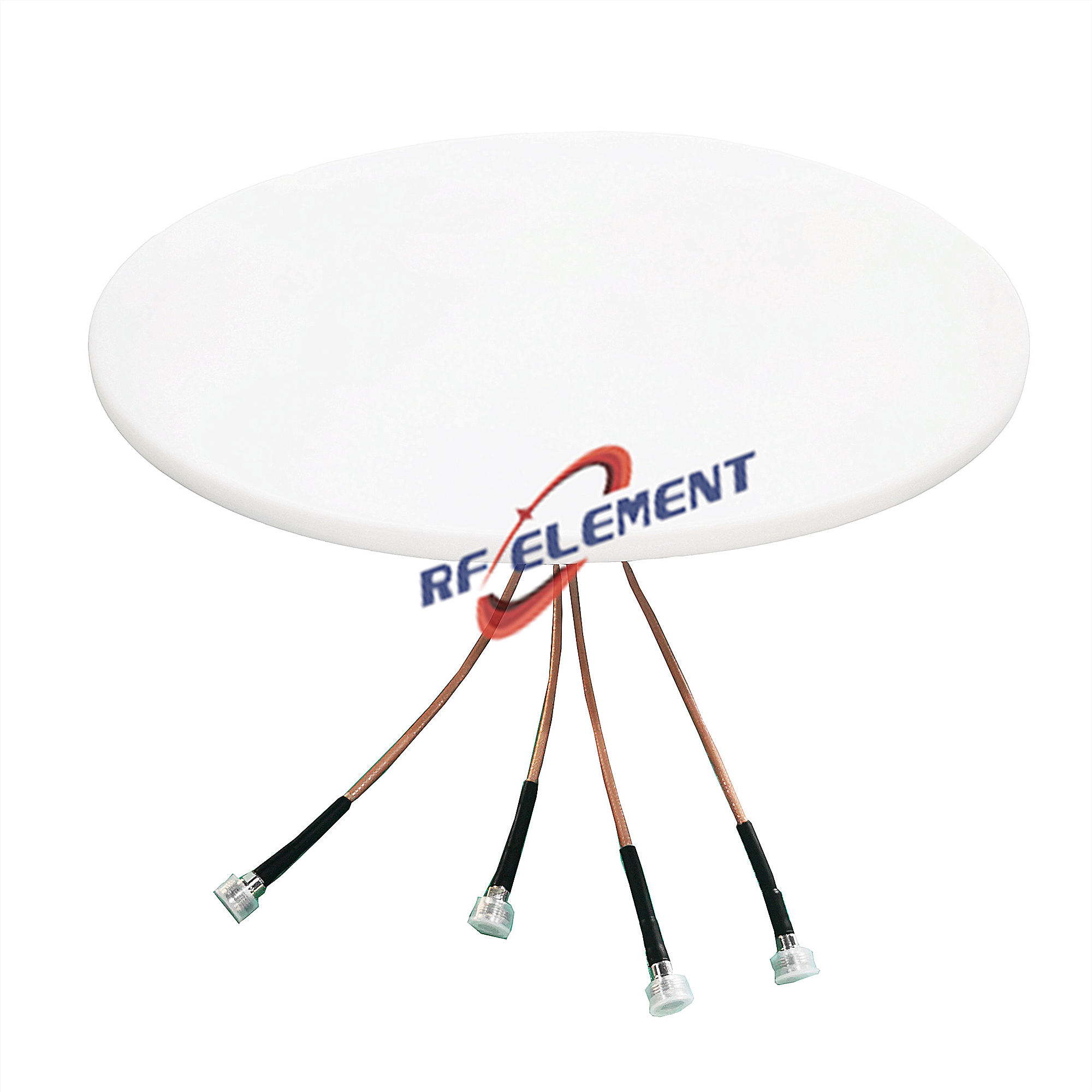
Compact 5G Ceiling Antenna | Low Profile Indoor Antenna 698-4200MHz
Specifications
A 180 mm ceiling antenna for installations where the radome is seen by the public and the brief says the smallest possible visual footprint. At 12 mm deep and 0.3 kg it sits inside a standard 600 mm ceiling grid without cutting a tile, and the single 4.3-10 or N-Type port keeps the cable schedule simple. Coverage is 360 degrees from 698 to 4200 MHz, with gain from 1.5 dBi at the low end to 5.5 dBi above 3.3 GHz.
What the small size costs
A 180 mm plate has less aperture than a 280 or 385 mm one, and the difference shows up as slightly wider vertical beamwidth rather than lower gain: 90 degrees at 698-806 MHz falling to 40 degrees at the top of the band. For a standard 3 m ceiling that is an advantage, because the pattern fills the floor between ceiling positions instead of overshooting into the next zone. For a high atrium it is a limitation, and a narrower-beam unit is the better choice.
The single port means SISO. Where the remote unit is 2x2 or 4x4, this antenna will only carry one stream, so it belongs on floors where capacity demand is moderate: meeting rooms, back-of-house corridors, small retail units, clinics, hotel public areas.
The sub-range most buyers miss
The table includes 1350-1550 MHz, which most ceiling antennas in this class omit. That window covers L-band satellite and GNSS repeaters, and in practice it means one ceiling unit can serve a cellular DAS and an indoor positioning or timing system instead of two separate antenna types. If the project has an indoor GPS repeater or a timing source that needs distribution, check that row before ruling this unit out on size alone.
| Frequency Range | 698-4200MHz | |||||
| Frequency Sub-Range(Mhz) | 698-806 | 806-960 | 1350-1550 | 1710-2700 | 3300-3800 | 3800-4200 |
| Polarization | Vertical | |||||
| Gain(dBi) | 1.5±0.5 | 2.2±0.5 | 3.5±0.5 | 4.5±0.5 | 5.5±0.5 | 5.5±0.5 |
| Horizontal Beam width | 360° | |||||
| Vertical Beam width | 90±10° | 85±10° | 65±10° | 40±20° | 40±20° | 40±20° |
| Impedance | 50Ω | |||||
| VSWR | ≤ 1.5 | ≤ 1.5 | ≤ 1.5 | ≤ 1.5 | ≤1.5 | ≤1.6 |
| 3rd Order for 2×20 W Carriers | -153 dBc | |||||
| Maximum Power | 50 W | |||||
| Connector Type | 1 Port, 4.3-10 Female or N-Type Female | |||||
| Length | 180 mm | |||||
| Width | 180 mm | |||||
| Depth | 12 mm | |||||
| Net Weight | 0.3 kg | |||||
| Operating Temperature | -55° to +60° C (-67° to +140° F) | |||||
| Radome Material | Plastic ABS | |||||
| Radome Color | White | |||||
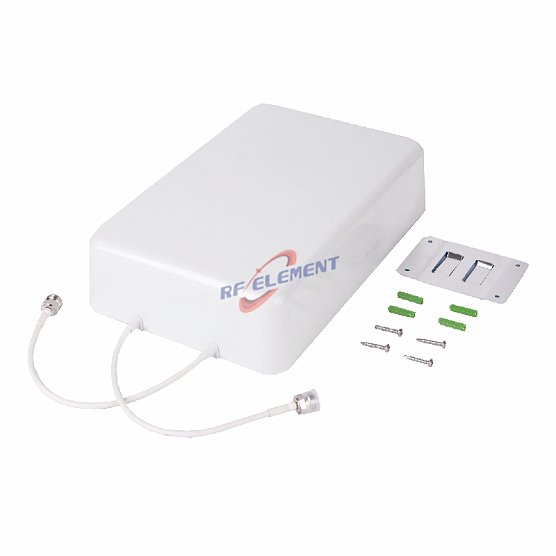
| Mounting Options | Fasteners and screws included for wall mounting | |||||
Return loss is at or below 1.5 across five of the six sub-ranges and 1.6 at 3800-4200 MHz, which is tighter than the 1.8 that most data sheets quote at the band edges. Third-order PIM of -153 dBc under two 20 W carriers is the same figure as the larger units in the range, so the small size does not come with a PIM penalty.
Installation notes
The radome fixes with fasteners and screws supplied, either into the ceiling grid or into a plasterboard ceiling with the appropriate anchor. Keep 200 mm clear of metal above the plate; at this size the pattern is more sensitive to nearby steel than a larger aperture would be. Avoid mounting directly under a luminaire driver, which is a common source of wideband noise at the low end of the band.
Because the unit is light, a drop wire to a single anchor point is usually enough, but the cable should still be supported independently within 150 mm of the connector so the joint does not carry the cable weight.
Where it fits in the range
If the ceiling void allows 15 mm rather than 12 mm and the project needs a larger aperture for a taller space, the 186 mm low PIM ceiling antenna carries the same 698-3800 MHz coverage at 0.3 kg with a larger radiating area. If two streams are required at the remote unit, the 2-port wideband version is the next step up at 280 mm square.
For projects that are primarily in-building cellular distribution, the DAS in-building antenna range page groups the units by ceiling void depth and port count.
Customisation and ordering
Connector type, radome colour and cable length are specified at order. The compact 180 mm form factor is fixed tooling; a smaller plate would require a new mould and is not offered as a variant. Samples in 3-5 days, production in 15-25 days.
Tell us the ceiling type, the mounting height and whether the band plan includes anything below 700 MHz or above 3.8 GHz. Those three answers decide whether this unit or the 186 mm low PIM version is the correct part number.
FAQ — Compact 5G Ceiling Antenna
What is the Compact 5G Ceiling Antenna used for?
What frequency band does the Compact 5G Ceiling Antenna cover?
What are the key specifications of the Compact 5G Ceiling Antenna?
Can RF element customize the Compact 5G Ceiling Antenna for my application?
What is the MOQ and lead time for the Compact 5G Ceiling Antenna?
How do I get a quotation for the Compact 5G Ceiling Antenna?