5G Ceiling Antenna | Low PIM Rated Antenna(-150dBc@2x20W) | Low Profile Antenna
Achieve exceptional wireless coverage with RF element's Low Profile 5G Slim Ceiling Antenna, designed for 5G, 4G LTE, 3G, and more. Our 3rd Order Low PIM antenna offers a sleek, space-saving design with a wide frequency range of 698-3800MHz. Ideal for DAS systems, it's easy to install and maintain. Get a quote now!
Specifications
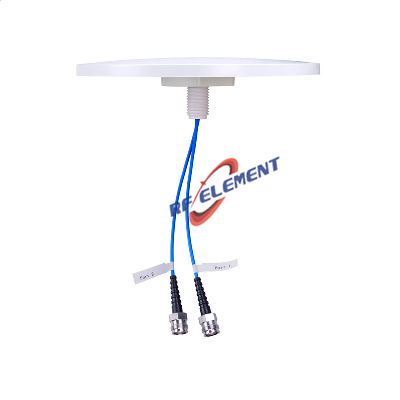
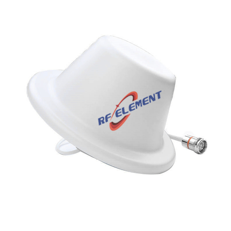
The smallest low PIM ceiling antenna in the range: a 186 mm disc, 15 mm thick, 0.3 kg, with a single 4.3-10 Female port and a third-order PIM of -150 dBc under two 20 W carriers. It exists for the case where the ceiling grid is dense and every position has to be small, light and identical, such as a hotel floor with a position every 8 metres or a hospital corridor with a unit above every doorway.
Dense grids, not long throws
Gain of 2.5 dBi in the two low sub-ranges and 4 dBi above 1.7 GHz is modest by design. A small aperture with moderate gain produces a wide vertical pattern, which is exactly what a dense grid needs: each unit covers the floor beneath it and hands over to the next, with no attempt to reach across the room. Where the design calls for 12 m spacing or a high atrium, this is the wrong unit and the 280 mm disc is the right one.
The upside of the dense layout is capacity. More positions means more remote unit ports, more even distribution and a lower power per antenna, which in turn keeps the PIM contribution of each antenna low. At 0.3 kg the ceiling load is negligible even at high density.
What -150 dBc buys
Intermodulation generated inside the antenna cannot be filtered out downstream, so the antenna's own PIM sets a floor on the whole system. -150 dBc under two 43 dBm carriers is the figure operators ask for on indoor passive layers, and it is met here at a size where many suppliers stop at -140 or -145 dBc. The maximum power rating of 50 W leaves margin above any indoor remote unit.
| Frequency Range | 698-3800MHz | |||
| Frequency Sub-Range(Mhz) | 698-806 | 806-960 | 1710-2700 | 3300-3800 |
| Polarization | Vertical | |||
| Gain(dBi) | 2.5 | 2.5 | 4.0 | 4.0 |
| Horizontal Beam width | 360° | |||
| Vertical Beam width | 90±10° | 85±10° | 65±10° | 40±20° |
| Impedance | 50Ω | |||
| VSWR | ≤ 1.8 | ≤ 1.5 | ≤ 1.5 | ≤ 1.5 |
| Maximum Power | 50 W | |||
| PIM, 3rd Order | -150dBc@2*43dBm | |||
| Connector | 4.3-10 Female | |||
| Dimension | φ186*15 mm | |||
| Net Weight | 0.3kg | |||
| Packing Size | 51*39*36cm(20 PCS) | |||
| Operating Temperature | -55° to +60° C (-67° to +140° F) | |||
| Radome Material | Plastic ABS | |||
| Radome Color | White | |||
| Mounting Options | fasteners and screws included for ceiling mounting | |||
Note that the PIM figure is stated as a relative value. If a competing data sheet quotes an absolute -97 dBm without stating the carrier power, the two numbers cannot be compared directly; ask for the test condition before treating one as better than the other.
Ceiling practice at 186 mm
The disc fits inside a 600 mm grid module with room to spare and can be offset toward the room side of the tile if the ceiling void has services on one side. Keep 200 mm clear of metal above it. On plasterboard, a single spring toggle is adequate for 0.3 kg plus cable, but the cable should still be independently supported within 150 mm of the connector.
Because the profile is only 15 mm, the unit can be fitted under a finished ceiling without removing neighbouring tiles, which matters in occupied buildings where access is scheduled out of hours.
Choosing the diameter
Same PIM, same profile, same connector as the 280 mm low PIM disc, which holds gain flatter across the mid band and suits sparser layouts. If the floor needs two streams rather than one, the dual polarized 215 mm unit is the next size up with a second polarization.
For a full list of indoor units by ceiling void and port count, see the DAS in-building antenna range page.
Customisation and ordering
Radome colour, cable length and packing are selectable. The 186 mm diameter and 15 mm depth are fixed tooling. Samples in 3-5 days, production in 15-25 days.
Send the ceiling height, the intended position spacing and the number of positions per floor. Spacing is the number that decides between this unit and the 280 mm disc.
FAQ — 5G Ceiling Antenna
What is the 5G Ceiling Antenna used for?
What frequency band does the 5G Ceiling Antenna cover?
What are the key specifications of the 5G Ceiling Antenna?
Can RF element customize the 5G Ceiling Antenna for my application?
What is the MOQ and lead time for the 5G Ceiling Antenna?
How do I get a quotation for the 5G Ceiling Antenna?