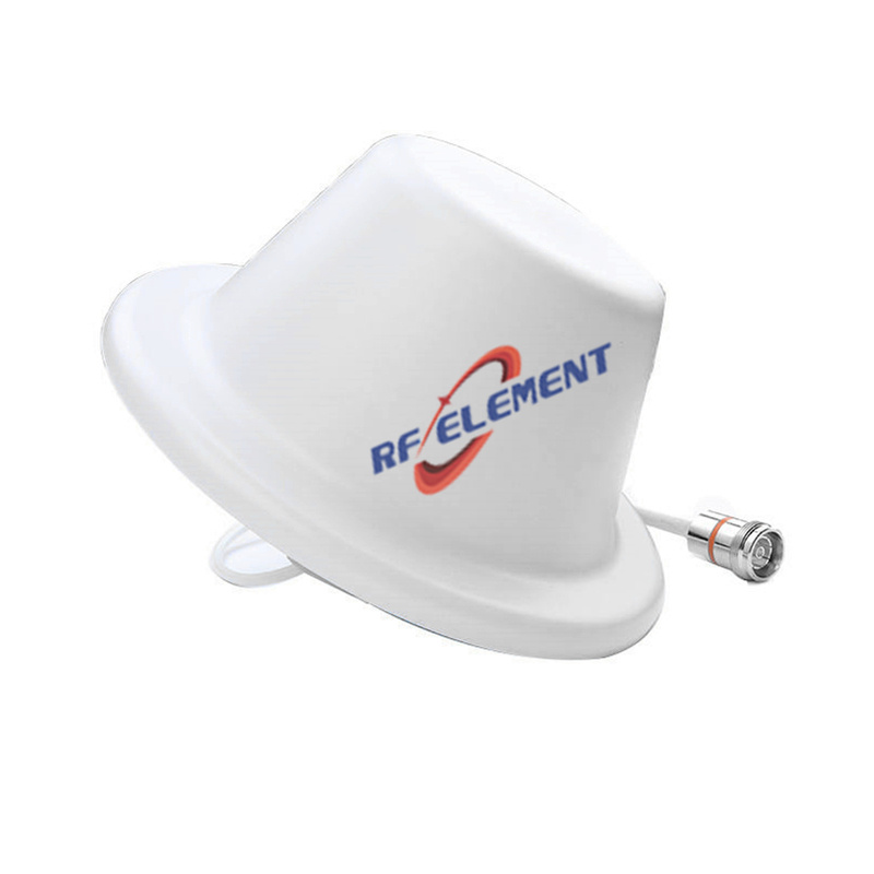
5G MIMO Ceiling Antenna | Low PIM Rated Antenna(-150dBc@2x20W) | Low Profile Antenna
Explore RF element's Low PIM 2x20W 5G MIMO Ceiling Antenna, designed for comprehensive wireless coverage from 698MHz to 3800MHz. This 3rd Order Low PIM antenna ensures superior communication quality with a sleek, low-profile design for easy installation in DAS systems. Ideal for 5G, 4G/LTE, and 3G applications. Contact us for expert advice and competitive pricing.
Specifications
A 280 mm disc that is 15 mm thick, aimed at ceilings where the coverage radius per position matters more than the port count. Gain runs from 2.5 dBi at 698-806 MHz to 4 dBi from 1.7 GHz upward, and the wide face keeps the vertical pattern broad enough that a 3 m ceiling produces one continuous coverage zone instead of a series of overlapping circles.
Diameter against depth
The 280 mm disc and the 186 mm disc in the same range carry identical PIM and connector ratings; the difference is aperture. A larger aperture concentrates the pattern slightly and holds gain flatter across the mid band, which is why this unit does not drop to 2.5 dBi above 1.7 GHz the way the smaller one does. In a corridor 3 m wide and 40 m long, that translates into fewer ceiling positions for the same signal level at the far end.
Both are 15 mm thick and both mount with the supplied fasteners. The choice between them is a layout decision, not a performance one: larger discs for open floors with sparse positions, smaller discs for dense grids and low ceilings.
Polarization as specified
The data sheet lists the polarization as linear plus horizontal. Read that literally before designing a 2x2 layer around it: the single 4.3-10 Female connector means one feed point, so the two linear components are not independent ports and should not be counted as two MIMO streams. Where the remote unit expects two physically separate ports, use a two-port plate instead.
| Frequency Range | 698-3800MHz | |||
| Frequency Sub-Range(Mhz) | 698-806 | 806-960 | 1710-2700 | 3300-3800 |
| Polarization | Linear +Horizontal | |||
| Gain(dBi) | 2.5 | 4.0 | 4.0 | 4.0 |
| Horizontal Beam width | 360° | |||
| Vertical Beam width | 90±10° | 85±10° | 65±10° | 40±20° |
| Impedance | 50Ω | |||
| VSWR | ≤ 1.8 | ≤ 1.5 | ≤ 1.5 | ≤ 1.5 |
| Maximum Power | 50 W | |||
| PIM, 3rd Order | -150dBc@2*43dBm | |||
| Connector | 4.3-10 Female | |||
| Dimension | φ280*15 mm | |||
| Net Weight | 0.5kg | |||
| Packing Size | 87*58*31cm(20 PCS) | |||
| Operating Temperature | -55° to +60° C (-67° to +140° F) | |||
| Radome Material | Plastic ABS | |||
| Radome Color | White | |||
| Mounting Options | fasteners and screws included for ceiling mounting | |||
What the single port does buy is simplicity. One cable per ceiling position, one connector to torque, one jumper to stock. On a large floor with a hundred positions, halving the cable count and the connector count is a real saving in both material and commissioning time.
PIM under load
Third-order PIM is -150 dBc under two 43 dBm carriers, which is the standard test condition for indoor DAS antennas and the figure most operators specify. It is measured at the antenna, so it represents what the antenna itself contributes and excludes anything generated in the cable or the connector. In practice the connector joint is the weaker element, which is why the installation notes below matter as much as the data sheet figure.
Maximum power is 50 W, well above what an indoor remote unit delivers per port, so thermal margin is not the constraint at this size.
Installation
Four fixing points around the rim, fasteners supplied. On a grid ceiling, fit a support wire to the grid tee rather than relying on the tile. Keep 250 mm clear of metal above the disc; at 280 mm diameter the pattern is less sensitive to nearby structure than a smaller plate, but a steel beam directly overhead will still flatten one side of the pattern.
Torque the 4.3-10 to the specified value and inspect the joint after the ceiling is closed. A 4.3-10 that is only hand-tight will pass a sweep at low power and fail PIM at operating power, which is the single most common commissioning fault on indoor systems.
Related units
For dense grids and low ceilings the 186 mm low PIM ceiling antenna uses the same 15 mm profile with a smaller footprint. Where two streams are needed at the remote unit, the dual polarized ceiling unit adds a second polarization within a 215 mm body.
Customisation and ordering
Radome colour, cable length and packing quantity are selectable; the connector is 4.3-10 Female as standard. The 698-3800 MHz span is fixed. Samples in 3-5 days, production in 15-25 days.
Send the floor plan with ceiling heights and the target signal level at the cell edge. That is enough to tell you whether this disc or the 186 mm version gives the lower installed cost per square metre.
FAQ — 5G MIMO Ceiling Antenna
What is the 5G MIMO Ceiling Antenna used for?
What frequency band does the 5G MIMO Ceiling Antenna cover?
What are the key specifications of the 5G MIMO Ceiling Antenna?
Can RF element customize the 5G MIMO Ceiling Antenna for my application?
What is the MOQ and lead time for the 5G MIMO Ceiling Antenna?
How do I get a quotation for the 5G MIMO Ceiling Antenna?