5G MIMO Panel Antenna | Low PIM Rated (-150dBc@2x20W) | 698-3800MHz
Achieve superior signal quality with our ultra-low PIM (-150dBc) 5G MIMO panel antenna. Covers 698-3800MHz, ideal for macro cells and sensitive RF environments. This 2x2 MIMO panel antenna is an ideal choice for indoor DAS systems and 5G signal boosting in enterprise environments. Contact us for a quote.
Specifications
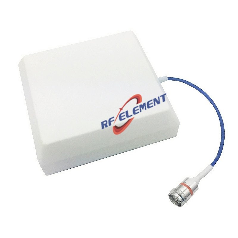
A two-port cross-polarised panel for outdoor DAS and small cell coverage that has to stay linear in the busiest part of the band. The 360 x 155 x 65 mm housing carries two 4.3-10 female ports on a +/-45 degree lattice, with 6 dBi at 698-960 MHz rising to 8 dBi at 1710-2700 MHz and 7 dBi at 3300-3800 MHz. Third-order PIM is quoted at -153 dBc under two 43 dBm carriers, and front-to-back behaviour is not specified at all, because this is a coverage panel rather than a sector antenna.
What the PIM figure actually commits you to
The datasheet line reads -153 dBc at 2 x 43 dBm. That is two carriers of 20 W each, measured at the antenna ports, which is the standard test condition for in-building distribution. It is not a statement that the antenna will hold -153 dBc at any power level. If the remote unit feeding it runs 40 W per carrier, the intermodulation products scale and the figure you can expect is roughly 6 dB worse, so a tender that specifies -153 dBc at 2 x 40 W is asking for a different part.
The practical consequence is simple: match the antenna PIM specification to the carrier power of the remote unit, not to the number that looks best on a comparison sheet. On a shared DAS where several operators inject into one antenna, the antenna is the one element that cannot be filtered downstream, so this is the specification worth arguing about.
Why the low band runs a 90 degree beam
At 698-960 MHz the radiating aperture is small in wavelengths, so a panel this size cannot form a narrow horizontal pattern without losing efficiency. The 90 degree figure at the bottom of the band is therefore a physical outcome, not a compromise in the design. It suits a wall or pole position that has to illuminate a wide face of a building or a section of street.
By 1710-2700 MHz the pattern tightens to 65 degrees, and at 3300-3800 MHz to 60 degrees. That progression is what you want when the same antenna has to serve a legacy 800 MHz operator and a 3.5 GHz small cell: the higher band reaches further on the same mounting point without a second antenna and a second cable run.
| Frequency Range | 698-3800MHz | ||
| Frequency Sub-Range(Mhz) | 698-960 | 1710-2700 | 3300-3800 |
| Polarization | ±45° | ||
| Gain(dBi) | 6 | 8 | 7 |
| Horizontal Beam width | 90±15° | 65±15° | 60±20° |
| Vertical Beam width | 85° | 60° | 55° |
| Impedance | 50Ω | ||
| VSWR | ≤ 1.8 | ≤ 1.8 | ≤1.8 |
| PIM, 3rd Order | -153 dBc@2x43dBm | ||
Isolation | -20dB | ||
| Maximum Power | 50 W | ||
| Connector Type | 2 Port, 4.3-10 Female | ||
| Dimension | 360*155*65 mm | ||
| Net Weight | 1.1 kg | ||
| Packing Size | 46*37*35 cm(10 pcs) | ||
| Radome Material | Plastic ABS | ||
| Operating Temperature | -55° to +60° C (-67° to +140° F) | ||
| Mounting Options | wall mounting or pole mounting(Optional) | ||
Isolation written as a negative number
The table lists isolation as -20 dB. Read it as 20 dB of port-to-port isolation, which is the usual way this parameter is entered in Chinese datasheets. Twenty decibels is adequate for a 2x2 MIMO branch where the two streams are already decorrelated by the cross-polarised lattice, but it is not enough to treat the two ports as independent radio chains for high order modulation without checking the error vector budget of the remote unit.
Where the same panel is used for a single carrier with transmit and receive on separate ports, 20 dB is on the low side and an external duplexer is the normal answer. Ask for the isolation at the specific sub-range you intend to use, because the table gives one number for the whole 698-3800 MHz span.
Mounting, weight and pattern control
At 1.1 kg and 65 mm deep, the panel fixes to a wall bracket or a pole with the hardware supplied. Keep the mounting point at least 300 mm from metal conduit, cable tray and structural steel on the radiating side; a coverage panel with a 90 degree low band pattern is less sensitive to nearby metal than a narrow sector, but the front-to-back behaviour in the low band is unspecified, and reflections off a parallel wall will fill in behind the unit.
For rooftop pole positions, aim the panel slightly downward rather than horizontally. The vertical beamwidth is 85 degrees at 698-960 MHz, so a small mechanical downtilt moves the coverage edge without creating a null in front of the antenna.
For a single-polarisation version of the same coverage idea, the SISO 698-3800 MHz panel uses one port at 0.4 kg and suits a remote unit that does not need two branches. The wider 5G antenna range groups the panels by port count and by band coverage.
Specifying it for a project
Connector type, radome colour and packing quantity are fixed at order. The 4.3-10 female interface is standard; an N-Type female variant is available on request. Samples are typically available in 3-5 days and production runs in 15-25 days.
Send the sub-ranges you actually need, the carrier power per port and the mounting height. Those three answers decide whether this panel or the single-port version is the correct part, and whether the PIM figure in your specification is being tested under conditions this antenna can meet.
FAQ — 5G MIMO Panel Antenna
What is the 5G MIMO Panel Antenna used for?
What frequency band does the 5G MIMO Panel Antenna cover?
What are the key specifications of the 5G MIMO Panel Antenna?
Can RF element customize the 5G MIMO Panel Antenna for my application?
What is the MOQ and lead time for the 5G MIMO Panel Antenna?
How do I get a quotation for the 5G MIMO Panel Antenna?