A low-PIM ceiling antenna is not a ceiling antenna with a better label. Third-order passive intermodulation is generated where two or more metal surfaces touch under current, so the -150 dBc figure on our indoor parts is a statement about joints, plating and the radiation element underneath the cover rather than about the cover itself. The requirement usually arrives in one shape: an operator or a systems integrator needs the indoor layer to stay quiet while several carriers share the same distributed antenna system. This is how we build for that, and what the numbers mean when you read them on a datasheet.
Why 150 dBc is a different kind of specification
PIM is measured by driving an antenna with two carriers and listening for a third-order product that lands back inside the receive band. Written as -150 dBc, the requirement is measured with two carriers of 20 W each, and the distortion limit sits 150 dB below the level of those carriers. Stated plainly, the antenna is allowed to create a signal a thousandth of a billionth of the power passing through it. Riveted construction does not reach that figure at any reasonable cost, which is why a low-PIM indoor antenna is designed backwards from the joints instead of forwards from the radiation pattern.
Three indoor parts, one PIM floor
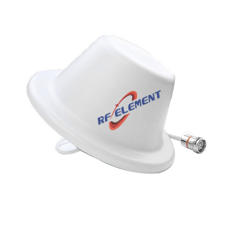
All three of our low-PIM ceiling antennas carry the same -150 dBc figure, with a pair of 20 W carriers applied, all three accept 50 W, all three hold VSWR at or under 1.8, all three present a 4.3-10 female connector, and each works the full 698-3800 MHz span, with 698-806 MHz named as the low sub-range. What separates them is geometry and stream count. The cellular ceiling antenna is the single-port part: vertical polarization, 1.5 dBi, 360 degrees in azimuth and 60±10 degrees in elevation, inside a white ABS cover measuring 186 mm across by 85 mm deep and weighing 0.3 kg. The low-profile disc holds the same full-circle azimuth, widens elevation to 90±10 degrees, nudges gain to 2.5 dBi, and collapses the cover to 15 mm. The MIMO low-profile part adds horizontal polarization for two streams inside the same 90±10 degree envelope, on a 280 mm disc of 0.5 kg.
Fifteen millimetres or eighty-five: a ceiling decision
The two flat parts and the deep part solve different problems, and the difference is not cosmetic. An 85 mm body puts the radiating element far enough below the ceiling plane that the ceiling itself does not sit inside the reactive near field, which is the reason a 60±10 degree elevation pattern behaves the way it was modelled. A 15 mm body is a compromise made for rooms where a visible fixture is unacceptable, and it pays for that by widening the elevation to 90±10 degrees. Both are legitimate choices. What is not legitimate is specifying the flat part for a room with a metal ceiling grid a few centimetres above it and expecting the pattern in the datasheet.
Copper, joints and the parts of PIM a datasheet cannot show
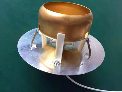
The two construction decisions behind our indoor parts are the radiating element itself and the cable assembly that feeds it. We use full copper radiating units, because conductivity at the radiating surface governs how much of the transmit current becomes heat or distortion instead of radiated power, and the difference between copper and a plated alternative is measurable at the third-order product. The cable and connector are made as one assembly matched to those elements rather than bought as separate items and mated afterwards — a low-PIM antenna with a generic jumper bolted to it is a low-PIM antenna only in the catalogue. This is also why the 4.3-10 interface appears across the whole line; the joint geometry of that connector class is friendlier to low distortion than an N-type pair of the same age.
Where a low-PIM part is the wrong answer
A low-PIM ceiling antenna costs more than an ordinary one, and four situations do not justify it. A single-carrier indoor link has no third-order product to suppress, so the requirement buys nothing. A room where the antenna sits well away from any other metal in the signal path already has a benign PIM environment, and a plain part will measure clean. A site whose real problem is coverage rather than distortion needs more elements or better placement, not a lower PIM floor. And a project that has not specified the connector and jumper to the same standard will lose the benefit at the first unplated interface, no matter what the antenna itself is rated at.
When the ceiling is the wrong elevation altogether
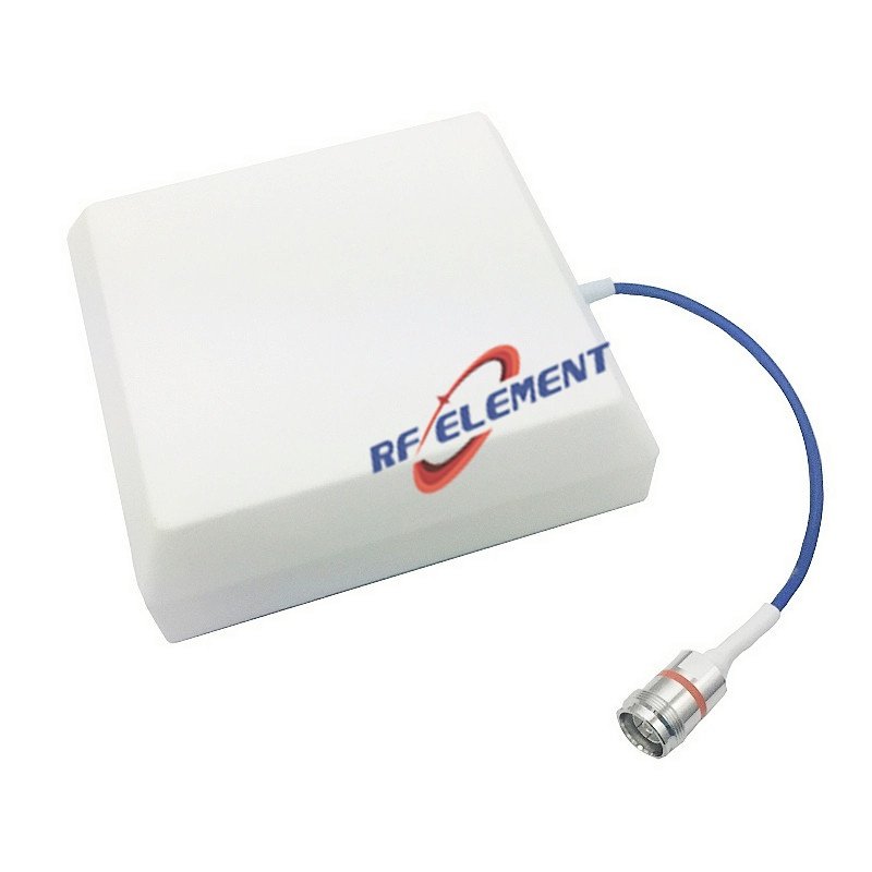
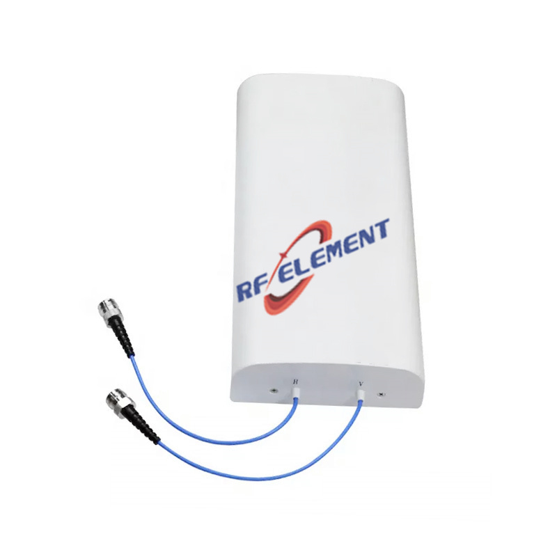
An indoor antenna radiating straight down is the correct answer in a hall, a concourse or an open office, and the wrong answer in a corridor, where the energy leaves through the two open ends and never covers the middle. The same applies under a mezzanine, where the ceiling plane is close enough to trap the pattern. For those shapes of building, the practical choice is a directional low-PIM panel aimed along the space: 6 dBi into a 90±15 degree horizontal and 85 degree vertical sector, third-order PIM at -153 dBc with the same two-carrier test, at least 10 dB between the front and back lobes, 50 W, one 4.3-10 female connector, and an ABS housing 165 mm wide, 155 mm tall and 45 mm deep at 0.4 kg. Where the indoor system also has to carry genuinely separate streams, the MIMO ceiling DAS part mounts a 215 by 215 by 41 mm plate at 0.8 kg with N-type female connections for both paths, 15 dB or better of isolation between them, and a third-order figure of -97 dBm against 2×2 W carriers. Where nothing above 2.7 GHz is involved, the 698-2700 MHz indoor disc handles last-metre distribution at 3 dBi across a 360 by 60 degree pattern, VSWR inside 1.5, fed by an N-type female termination.
The cable is where a PIM specification usually dies
An indoor antenna is only as quiet as the jumper between it and the distribution point. A low-PIM antenna attached to an ordinary coaxial assembly inherits the intermodulation of that assembly, and the joint at the connector is where most of it is generated: a hand-tightened interface, a poorly plated body, or two dissimilar metals in contact under load. This is why the cable and connector leave our factory as part of the antenna rather than as something the installer sources locally. It also explains a pattern in the complaints we receive — a part returned as faulty that measures at specification on the bench and only misbehaves once it is in the ceiling, where the real fault sat in the mating hardware.
What we need to quote an indoor part
Give us the band plan, how many carriers share the system, the ceiling height and its material, and whether one stream is enough or two are needed. Our answer names the part, attaches the specification sheet, and flags any pattern or intermodulation risk the room layout creates. Prototypes go out a few days after drawing release, production dates follow the quantity we agree, and the minimum order is kept small enough that one floor can be fitted and measured before the full building is staged. Send the room details to sales@rfelement.com; the carriers in your plan are the carriers we test against.
TAG:The Low PIM Ceiling Antenna Solution https://www.rfelement.com