4G LTE Ceiling Antenna | Indoor Booster Antenna | 698-2700MHz
Specifications
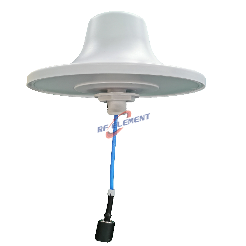
A 185 mm ceiling disc for indoor distributed antenna systems, covering 698-2700 MHz with 3 dBi at the low band and 5 dBi at the high band. The horizontal pattern is a full 360 degrees, the vertical beam is 60 degrees below 960 MHz and 30 degrees above 1710 MHz, VSWR stays at or below 1.5, and the single port is an N-Type female on a 50 W rating. The radome is white ABS, the unit weighs 0.4 kg, and fasteners for a wall or ceiling fixing are supplied.
One aperture, two beamwidths
The 185 mm disc is 0.43 wavelength at 700 MHz and 1.6 wavelength at 2.6 GHz. Electrical size sets beamwidth, so the vertical beam narrows from 60 degrees to 30 degrees as the frequency rises and the gain rises with it, from 3 dBi to 5 dBi. Both figures appear on one datasheet because both describe one antenna, not two.
That is why a single ceiling unit can serve a 700 MHz band and a 2.6 GHz band without a diplexer. The pattern changes with frequency, but the match does not. VSWR is held at or below 1.5 across the whole span, so the same feeder and the same connector work on both bands.
What 60 degrees does on a 3 m ceiling
With the beam edge 30 degrees below the horizon, a 3 m ceiling puts the half power line on the floor about 5 m from the antenna. The 30 degree beam at 2.6 GHz reaches the floor about 11 m out, so the high band covers a ring rather than a disc. Inside that ring the high band is fed by sidelobes and reflections, which is adequate in a small room but is not the main beam.
The practical rule is to mount the unit off centre in a long room or a corridor, so the narrow high band beam runs along the length of the space. Centred on a square ceiling, most of the 2.6 GHz energy is spent on the walls.
| Frequency Range | 698-2700MHz | |
| Frequency Sub-Range | 698-960 MHz | 1710-2700 MHz |
| Polarization | Vertical | |
| Gain(dBi) | 3 | 5 |
| Horizontal Beamwidth | 360° | |
| Vertical Beamwidth | 60° | 30° |
| Impedance | 50Ω | |
| VSWR | ≤1.5 | |
| Maximum Power | 50W | |
| Connector Type | 1 Port, N-Type Female | |
| Antenna Dimension(mm) | Φ 185*90 | |
| Net Weight | 0.4 kg | |
| Operating Temperature | -55° to +60° C (-67° to +140° F) | |
| Radome Material | ABS | |
| Radome Color | White | |
| Mounting Options | Fasteners and screws included for wall mounting | |
Floor to floor isolation
At 700 MHz a concrete slab attenuates less than at 2.6 GHz, so the low band leaks upward more than the high band does. In a multi floor building this matters when the same physical cell identity is reused on adjacent floors: the ceiling antenna in the floor above becomes an interfering source at 700 MHz even though it is well behaved at 2.6 GHz.
The usual fix is a plan change rather than a hardware change. Alternate the low band cells between floors, or reduce the remote head power on the low band port. The antenna cannot filter for you, but a predictable 60 degree beam lets you place the cells far enough apart to plan around the leak.
0.4 kg on a drop ceiling
The load is 0.4 kg plus the pigtail, so a T-bar clip or a plasterboard anchor is enough. The fasteners supplied suit a solid wall or a solid ceiling. For a suspended grid use a T-bar clip and a short safety tie so the unit cannot drop if a tile lifts.
Keep the N-Type connector reachable. The radome is sealed ABS and needs no service, but the connector is the one joint that has to be inspected, and a ceiling void is easier to work in through a lift out tile than through a cut hole.
Power, PIM and the 50 W rating
50 W is the rating of the connector and the internal feed, not a target. A DAS remote head usually delivers 20 to 40 W per port, so the margin is real but not large. Add up the composite power if two carriers share the port rather than reading the figure per carrier.
This unit is not specified as low PIM. Where a 700 MHz downlink and an 800 MHz uplink share a mast, order the 150 dBc version instead. Passive intermodulation is generated in the connector and the joint rather than in the radome, so the low PIM variant with a 7/16 DIN interface is the part that actually solves it.
Ordering
N-Type female is standard, the radome colour is white, and packing quantity is confirmed at order. Samples in 3-5 days, production in 15-25 days.
For a wider 698-4200 MHz span in the same ceiling format with two polarizations, the 5G ceiling antenna 698-4200 MHz uses the same fixing pattern. For outdoor coverage on the same band plan, the 4G LTE MIMO omni antenna 698-2700 MHz is the pole mounted counterpart.
Send the ceiling height, the band plan and the remote head power per port. The height sets the floor radius, the band plan decides whether one disc is enough, and the power decides whether the 50 W rating leaves the margin you need.
FAQ — 4G LTE Ceiling Antenna
What is the 4G LTE Ceiling Antenna used for?
What frequency band does the 4G LTE Ceiling Antenna cover?
What are the key specifications of the 4G LTE Ceiling Antenna?
Can RF element customize the 4G LTE Ceiling Antenna for my application?
What is the MOQ and lead time for the 4G LTE Ceiling Antenna?
How do I get a quotation for the 4G LTE Ceiling Antenna?