4G LTE MIMO Omni Antenna | 698-2700 MHz Outdoor Omni Antenna
Specifications
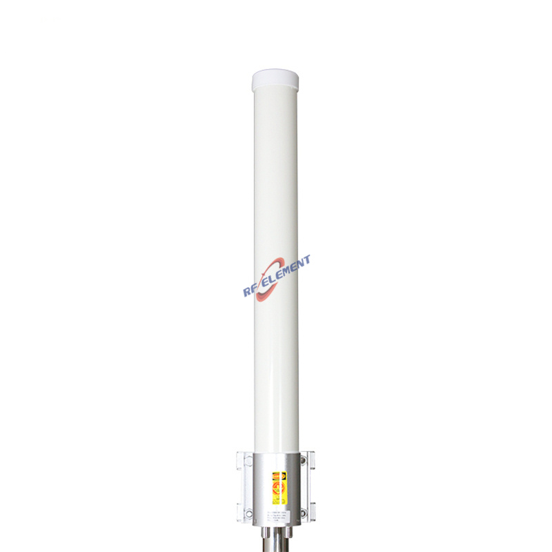
A 700 mm pole mounted omni for 698-2700 MHz with two N-Type female ports and a 100 W rating. Gain is 4 dBi at 698-960 MHz and 6 dBi at 1710-2700 MHz, the horizontal pattern is a full 360 degrees, the vertical beam is 60 degrees and 55 degrees, VSWR is at or below 2.0, and the radome is white ABS at 2.0 kg. It is built for point to multipoint links that need two data streams from a single pole position.
Two ports, one polarization
MIMO does not require a cross polarized pair. Two vertically polarized ports set apart along the 700 mm axis see slightly different multipath, and that difference is what the baseband uses. At 2.6 GHz the spacing is close to 6 wavelength; at 700 MHz it is 1.6 wavelength, which is enough for diversity but not enough for the full spatial multiplexing gain.
The honest expectation is therefore band dependent. In the high band, expect a usable second stream in a scattering environment. In the low band, expect diversity gain and a more stable link rather than a doubling of throughput. A radio that reports rank 2 at 2.6 GHz may report rank 1 at 700 MHz on the same antenna, and that is normal.
700 mm and the 6 dBi ceiling
Gain on an omni comes from vertical aperture. A half wave element gives about 2 dBi, and each additional collinear element adds roughly 2 to 2.5 dB while narrowing the vertical beam. The 700 mm radome holds enough elements for 6 dBi at 2.6 GHz and 4 dBi at 700 MHz, where the same length is a much smaller number of wavelengths.
The 55 degree beam at the high band is the widest in the outdoor 4G omni group after the dome, which is deliberate. A narrow beam on a pole mount produces a dead ring at the base of the mast; 55 degrees keeps the near field usable while the 6 dBi still reaches the far edge of a small cell.
| Frequency Range | 698-2700MHz | |
| Frequency Sub-Range | 698-960 MHz | 1710-2700 MHz |
| Polarization | Vertical | |
| Gain(dBi) | 4 | 6 |
| Horizontal Beamwidth | 360° | |
| Vertical Beamwidth | 60° | 55° |
| Impedance | 50Ω | |
| VSWR | ≤ 2.0 | |
| Maximum Power | 100W | |
| Connector Type | 2 Port, N-Type Female | |
| Antenna Dimension(mm) | Φ 75*700 | |
| Net Weight | 2.0 kg | |
| Operating Temperature | -55° to +60° C (-67° to +140° F) | |
| Radome Material | ABS | |
| Radome Color | White | |
| Mounting Options | Pole mounting | |
Wind load on a 75 mm section
The frontal area is 0.075 m by 0.7 m, about 0.05 square metres. At 40 m per second that is roughly 50 N of drag plus the moment arm of the mast clamp, which is well inside the capacity of a 40 mm pole and a standard two bolt clamp. The figure to check is the pole, not the antenna: a thin walled aluminium pole that is already carrying a sector will twist before the clamp slips.
Mount with the connector at the bottom. Water runs down a vertical radome, and a bottom entry connector with a weather boot keeps the joint dry without relying on tape.
The 360 degree ring in point to multipoint
For a rural cluster, a marina or a small industrial estate, one omni on a mast serves every subscriber inside the ring, and the ring radius is set by the radio power rather than by the antenna. What the antenna contributes is consistency: equal gain in every direction means the link budget does not change as a subscriber moves around the site.
That consistency is worth more than 2 dB of extra gain on a sector. A sector with 12 dBi reaches further in one direction, but a subscriber outside the 90 degree window is lost, and in a cluster the subscriber positions are fixed by buildings rather than by your plan.
Installation and cable
Two N-Type female ports mean two feeders, and feeder loss at 2.6 GHz is the dominant loss in most installations. Use 1/2 inch foam cable for runs up to 20 m and 7/8 inch for longer runs, and keep both jumpers the same length so the two chains stay phase matched.
The radome is ABS and the operating range is -55 to +60 C. In a coastal site, rinse the clamp and the connector boot at each service visit; the radome itself does not need treatment.
Ordering
Two N-Type female ports, white radome, pole clamp included. Samples in 3-5 days, production in 15-25 days.
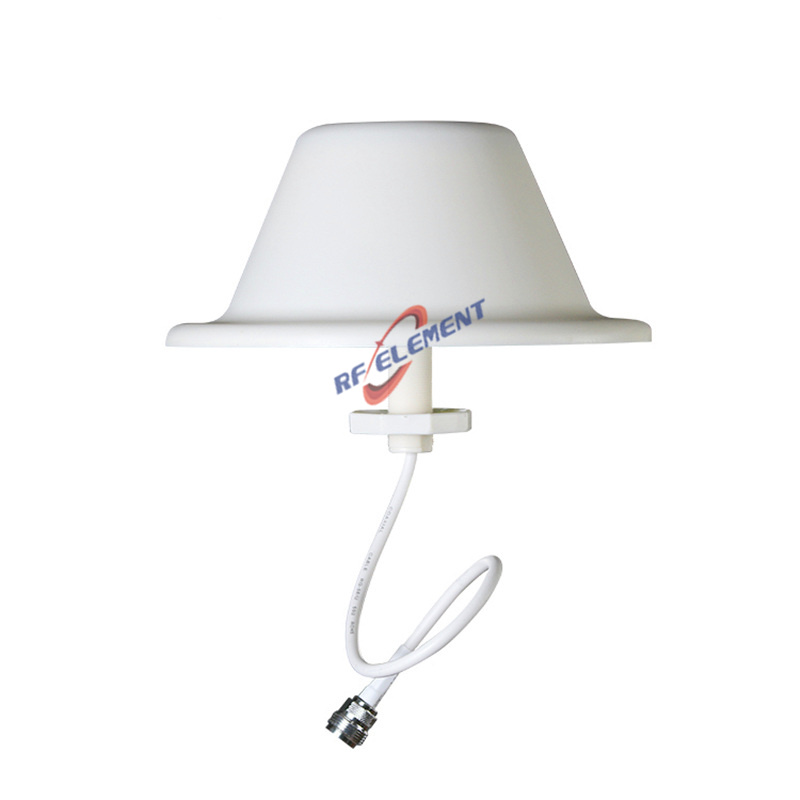
Where the pole height is limited and the site needs a lower profile, the 4G LTE MIMO dome omni antenna 800-2600 MHz is 150 mm tall and covers the same bands. Where the link needs directivity instead of a ring, the 4G LTE MIMO sector antenna 698-2700 MHz puts the same power into 65 degrees.
Send the band plan, the radio rank behaviour and the pole height. If the site is a cluster, say so: a ring is the right pattern, and a sector is not.
FAQ — 4G LTE MIMO Omni Antenna
What is the 4G LTE MIMO Omni Antenna used for?
What frequency band does the 4G LTE MIMO Omni Antenna cover?
What are the key specifications of the 4G LTE MIMO Omni Antenna?
Can RF element customize the 4G LTE MIMO Omni Antenna for my application?
What is the MOQ and lead time for the 4G LTE MIMO Omni Antenna?
How do I get a quotation for the 4G LTE MIMO Omni Antenna?