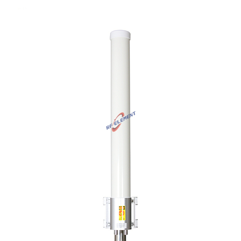
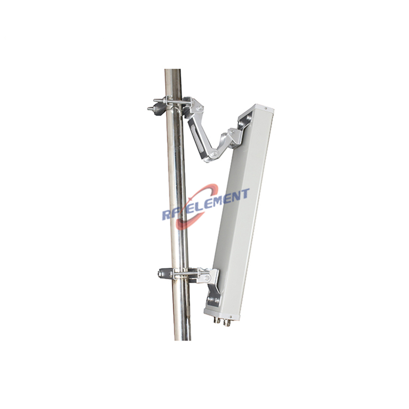
4G LTE MIMO Omni Antenna | Dome Omni Antenna,800-2600MHz
Specifications
A 210 mm dome, 150 mm tall, covering 800-2600 MHz with slant 45 degree polarization and two N-Type female ports. Gain is 4 dBi at 800-960 MHz and 6 dBi at 1710-2600 MHz, the horizontal pattern is a full 360 degrees, the vertical beam is 70 degrees and 40 degrees, VSWR is at or below 1.8, and the rating is 100 W. The unit weighs 1.0 kg and mounts on a pole, which makes it the low profile choice where a 700 mm sleeve will not pass.
Why a dome instead of a sleeve
A sleeve omni builds gain along its length. A dome builds it across a small ground plane, so the pattern is wider and the gain is lower for the same band. The trade is height against beamwidth: 150 mm of dome against 700 mm of sleeve, and 70 degrees of vertical beam at 800 MHz instead of 60 degrees.
Wider beam means the unit tolerates a mounting height that was not chosen for it. On a lamp post, a parapet or a pole shared with a camera, the height is set by something else. In that situation a 70 degree beam that illuminates the ground from an arbitrary height is more useful than 2 dB of gain aimed over the heads of the users.
Slant 45 on a 360 degree pattern
The two ports are fed at plus 45 and minus 45 degrees. Rotating the polarization does not change the azimuth pattern, which stays a full 360 degrees on both ports. What it changes is the orientation of the field, and therefore how well the antenna couples to a handset or a vehicle antenna whose orientation is unknown.
For a fixed subscriber unit with a known vertical antenna, a vertical pair would give a slightly better match. For a dome on a pole serving pedestrian or vehicle traffic, the slant pair is the more robust choice, because a 45 degree rotation costs about 3 dB at worst and a 90 degree rotation costs much more.
| Frequency Range | 800-2600MHz | |
| Frequency Sub-Range | 800-960 MHz | 1710-2600 MHz |
| Polarization | ±45° | |
| Gain(dBi) | 4 | 6 |
| Horizontal Beamwidth | 360° | |
| Vertical Beamwidth | 70° | 40° |
| Impedance | 50Ω | |
| VSWR | ≤ 1.8 | |
| Maximum Power | 100W | |
| Connector Type | 2 Port, N-Type Female | |
| Antenna Dimension(mm) | Φ 210*150 | |
| Net Weight | 1.0 kg | |
| Operating Temperature | -55° to +60° C (-67° to +140° F) | |
| Radome Material | ABS | |
| Radome Color | White | |
| Mounting Options | Pole mounting | |
150 mm and the wind
The frontal area is 0.21 m by 0.15 m, about 0.03 square metres, and the mass is 1.0 kg. That combination survives a pole that a 700 mm sleeve would load visibly, which is the reason domes end up on street furniture and on building parapets where the fixing is a single bracket.
Ice is the case to think about rather than wind. A dome holds snow on its upper surface, and 100 mm of ice on a 0.03 square metre top adds about 3 kg. Specify a bracket rated for 10 kg if the site sees snow, and keep the connector on the underside so melt water drains away from the joint.
800-2600 MHz and the missing 100 MHz
The low sub range starts at 800 MHz rather than 698 MHz. That covers the 800 MHz public safety and cellular allocations and the 900 MHz band, but it does not cover the 700 MHz band that many 4G networks now use as a coverage layer. If the site needs 700 MHz, this is not the part.
That single fact decides most enquiries. Where the operator has 700 MHz in service, the 698-2700 MHz sleeve or the 698-2700 MHz sector is the correct choice. Where the band plan starts at 800 MHz, the dome gives the same coverage with less visual impact and less wind load.
Pole mount and cable dressing
Two N-Type female ports exit the base. Keep 200 mm of clearance from a metal pole: at 800 MHz a pole inside a quarter wavelength of the radome distorts the pattern and can fill the null that keeps the antenna from radiating straight up.
Dress both jumpers down the pole and tie them at 300 mm intervals. A loose jumper on a 210 mm dome acts as a small reflector, and the effect is visible at 2.6 GHz even though it is invisible at 900 MHz.
Ordering
Two N-Type female ports, white ABS radome, pole mount. Samples in 3-5 days, production in 15-25 days.
Where the band plan includes 700 MHz, the 4G LTE MIMO omni antenna 698-2700 MHz covers the full span in a 700 mm sleeve. Where the site needs a sector pattern rather than a ring, the 4G LTE MIMO sector antenna 698-2700 MHz uses the same slant pair in a directional housing.
Send the band plan and the mounting height. If 700 MHz is in service, say so first, because it rules this antenna out before any other question matters.
FAQ — 4G LTE MIMO Omni Antenna
What is the 4G LTE MIMO Omni Antenna used for?
What frequency band does the 4G LTE MIMO Omni Antenna cover?
What are the key specifications of the 4G LTE MIMO Omni Antenna?
Can RF element customize the 4G LTE MIMO Omni Antenna for my application?
What is the MOQ and lead time for the 4G LTE MIMO Omni Antenna?
How do I get a quotation for the 4G LTE MIMO Omni Antenna?