5G MIMO Ceiling Antenna | 5G DAS Antenna | 698MHz-3800MHz
Specifications
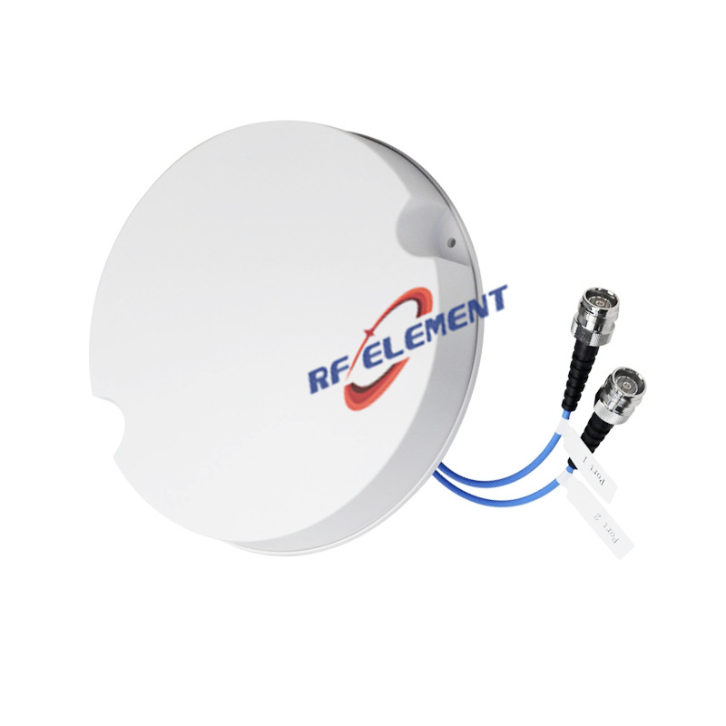
A 215 mm ceiling antenna with a 41 mm deep body, built for ceilings where the void above the tile is too shallow for a flat plate and too tight for a recessed can. The two N-Type Female ports sit on the underside, so the cable exits straight down into the ceiling grid rather than sideways through a cut tile edge. Coverage is 360 degrees from 698 to 3800 MHz with gain between 2 and 5 dBi depending on the sub-range.
Depth as a design decision
Most indoor ceiling antennas are either flat plates 12-18 mm thick or recessed units that need 80-120 mm of clear void. The 41 mm body sits between the two. It clears a standard 38 mm grid tee with a few millimetres to spare, which means it can be fitted from below without removing tiles, and it does not need a mounting can or a fire-rated enclosure.
The cost of that depth is weight: 0.8 kg against 0.3-0.5 kg for the flat plates. On a grid ceiling that is still within the capacity of a standard clip, but on a plasterboard ceiling the anchor should be rated for at least three times that figure.
Reading the PIM figure correctly
The third-order intermodulation specification here is given as -97 dBm under two 2 W carriers, not as a dBc figure. The two are not interchangeable: dBm is an absolute level at the antenna port, dBc is relative to the carrier power, and a -97 dBm result measured with 2 W carriers corresponds to a different dBc value than the -150 dBc figure quoted elsewhere in the range under 20 W carriers. When comparing this unit against a -150 dBc part, ask for the carrier power and the measurement setup, otherwise the comparison is between two different tests.
| Frequency Range | 698-3800MHz | |||
| Frequency Sub-Range(Mhz) | 698-806 | 806-960 | 1710-2700 | 3300-3800 |
| Polarization | Vertical | |||
| Gain(dBi) | 2±1 | 3±1 | 4±1 | 5±1 |
| Horizontal Beam width | 360° | |||
| Vertical Beam width | 85±10° | 75±10° | 65±10° | 50±10° |
| Impedance | 50Ω | |||
| VSWR | ≤ 1.5 | ≤ 1.5 | ≤ 1.5 | ≤ 1.5 |
| 3rd Order for 2×2 W Carriers | ≤-97 dBm | |||
| Isolation | ≥ 15dB | ≥ 18 dB | ≥ 18 dB | ≥ 20 dB |
| Maximum Power | 50 W | |||
| Connector Type | 2 Port, N-Type Female | |||
| Length | 215 mm | |||
| Width | 215 mm | |||
| Depth | 41 mm | |||
| Net Weight | 0.8 kg | |||
| Operating Temperature | -55° to +60° C (-67° to +140° F) | |||
| Radome Material | Plastic ABS | |||
| Radome Color | White | |||
| Mounting Options | Fasteners and screws included for wall mounting | |||
This matters most in a shared DAS. If the site is a single-operator small cell, the absolute figure is the practical one, because what reaches the receiver is an absolute level. If the site is a multi-operator neutral host with high carrier power per port, the relative figure is the one that predicts whether the antenna will generate interference.
Coverage pattern
Gain rises from 2 dBi at 698-806 MHz to 5 dBi at 3300-3800 MHz, and vertical beamwidth narrows from 85 to 50 degrees over the same span. In a room with a 3 m ceiling that gives overlapping coverage at about 4 m centres in the low band and slightly wider spacing in the high band, which is the opposite of what most installers assume. Where the high band carries most of the traffic, keep the spacing set by the low band and accept the overlap.
Port isolation is 15-20 dB across the range, highest at 3.3-3.8 GHz. The 2x2 MIMO arrangement is well separated at the top of the band and adequate in the middle, which is typical for a body this size.
Mounting and cabling
The N-Type Female connectors point down, so a right-angle or a short flexible jumper is usually needed to route the cable along the grid. Keep the first 150 mm of cable supported and avoid a tight bend radius directly at the connector, which is the most common cause of a PIM failure found at commissioning.
Where the ceiling is genuinely flat and 15 mm is available, the 280 mm wideband plate gives the same port count with better return loss and half the weight. Where the installation is a public building with a fixed ceiling grid and no access above, this 41 mm body is the one that fits.
Customisation and ordering
Connector type is fixed as N-Type Female on this model; 4.3-10 is available on the flat-plate versions. Radome colour and packing quantity are selectable. Samples in 3-5 days, production in 15-25 days.
Send the ceiling void depth, the tile module and the carrier power per port. The void depth decides between this unit and a flat plate, and the carrier power decides which PIM figure you should be comparing.
FAQ — 5G MIMO Ceiling Antenna
What is the 5G MIMO Ceiling Antenna used for?
What frequency band does the 5G MIMO Ceiling Antenna cover?
What are the key specifications of the 5G MIMO Ceiling Antenna?
Can RF element customize the 5G MIMO Ceiling Antenna for my application?
What is the MOQ and lead time for the 5G MIMO Ceiling Antenna?
How do I get a quotation for the 5G MIMO Ceiling Antenna?