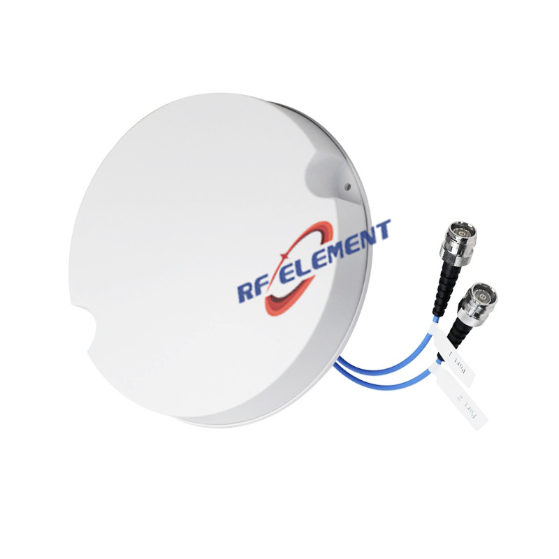
5G Cellular Ceiling Antenna | Low PIM Rated Antenna(-150dBc@2x20W), 698-3800 MHz
Elevate your in-building wireless network with RF element's Low PIM Rated 5G DAS Ceiling Antenna. With a broad 698-3800MHz frequency range and 3rd Order low PIM performance, this dome ceiling antenna ensures superior signal quality for 5G, 4G/LTE, and Wi-Fi applications. Perfect for DAS antenna systems, it's designed for quick installation and reliable coverage. Contact us for expert advice and pricing.
Specifications
A 186 mm ceiling antenna with a 85 mm body and the narrowest vertical pattern in this range: 60 degrees at 698-806 MHz, tightening to 30 degrees across 1710-2700 MHz. That shape is not an accident of the housing depth. It is what you specify when the ceiling is high, the floor plate is large, and the design needs each position to throw further rather than spread wider.
Narrow pattern, specific use
Most indoor ceiling units spread energy over 65-90 degrees vertically so that a 3 m ceiling produces even coverage without blind spots at the installer's feet. A 30 degree pattern at mid band behaves differently: the main beam reaches further along the floor, and the region directly below the antenna receives less. In a warehouse with a 9 m ceiling, a station concourse or an exhibition hall, that is the correct behaviour, because nobody needs coverage at the roof structure and the far end of the hall does need it.
In a 3 m office it is the wrong unit. The pattern will leave a ring of weaker coverage between positions, and no amount of remote unit power will fill it evenly. Height is the deciding variable here, not floor area.
Gain shape across the band
Gain is 1.5 dBi at 698-806 MHz, 2.0 dBi at 806-960 MHz, 5.0 dBi at 1710-2700 MHz and 4.0 dBi at 3300-3800 MHz. The peak sits in the mid band, which is unusual: most units in this class peak at the top of the band. The mid-band peak matches where most indoor traffic sits today, and the 4 dBi at 3.3-3.8 GHz is still enough for a 5G layer at moderate spacing.
| Frequency Range | 698-3800MHz | |||
| Frequency Sub-Range(Mhz) | 698-806 | 806-960 | 1710-2700 | 3300-3800 |
| Polarization | Vertical | |||
| Gain(dBi) | 1.5 | 2.0 | 5.0 | 4.0 |
| Horizontal Beam width | 360° | |||
| Vertical Beam width | 60±10° | 50±10° | 30±10° | 40±20° |
| Impedance | 50Ω | |||
| VSWR | ≤ 1.8 | ≤ 1.5 | ≤ 1.5 | ≤ 1.8 |
| Maximum Power | 50 W | |||
| PIM, 3rd Order | -150dBc@2*43dBm | |||
| Connector | 4.3-10 Female | |||
| Dimension | φ186*85 mm | |||
| Net Weight | 0.3 kg | |||
| Packing Size | 78*34*38cm(20 PCS) | |||
| Operating Temperature | -55° to +60° C (-67° to +140° F) | |||
| Radome Material | Plastic ABS | |||
| Radome Color | White | |||
| Mounting Options | fasteners and screws included for ceiling mounting | |||
Return loss stays at or below 1.5 across all four sub-ranges and relaxes to 1.8 at the band edges, and the third-order PIM of -150 dBc under two 43 dBm carriers is the same standard as the flat discs in the range. The 50 W rating covers any indoor remote unit.
Fitting an 85 mm body
Eighty-five millimetres needs a suspended ceiling with a clear void, or a surface mount on a concrete soffit. It will not fit between a plasterboard ceiling and a concrete slab with no service gap. Where the void is only 20 mm, this unit is not an option regardless of its pattern.
The single 4.3-10 Female port exits from the base. On a high ceiling, support the cable at the first 300 mm and use a strain relief independent of the connector, because a long vertical drop puts load on the joint. Where the ceiling is accessible only by lift, fit the jumper before lifting the unit into place.
Compare before ordering
If the ceiling is below 4 m, the 15 mm flat disc gives a wide pattern at a third of the depth. If the ceiling is high and the band plan stops at 3.8 GHz, this unit's mid-band gain is the reason to choose it. For a space where the requirement is even coverage rather than reach, the cellular ceiling version is the alternative with a wider pattern at the same diameter.
Customisation and ordering
Radome colour, cable length and packing quantity are selectable. The 85 mm body and the beam shape are fixed by the internal structure. Samples in 3-5 days, production in 15-25 days.
Send the mounting height and the intended position spacing. At 9 m with 30 degree beamwidth the geometry gives roughly 20 m between positions before the pattern stops overlapping; at 3 m the same unit needs positions far closer than a standard grid allows.
FAQ — 5G Cellular Ceiling Antenna
What is the 5G Cellular Ceiling Antenna used for?
What frequency band does the 5G Cellular Ceiling Antenna cover?
What are the key specifications of the 5G Cellular Ceiling Antenna?
Can RF element customize the 5G Cellular Ceiling Antenna for my application?
What is the MOQ and lead time for the 5G Cellular Ceiling Antenna?
How do I get a quotation for the 5G Cellular Ceiling Antenna?