5G Indoor Antenna | Low PIM Rated Antenna(-150dBc@2x20W), 698-4000 MHz
Enhance indoor 5G coverage with our professional 5G indoor antenna. Supports 698-4000MHz, ultra-low PIM (-150dBc). As a high-performance 5G indoor antenna, it's meticulously engineered for low PIM ratings of -150dBc@2x20W, ideal for DAS and ceiling mounting. Boost 5G/LTE signals in buildings. Get a quote!
Specifications
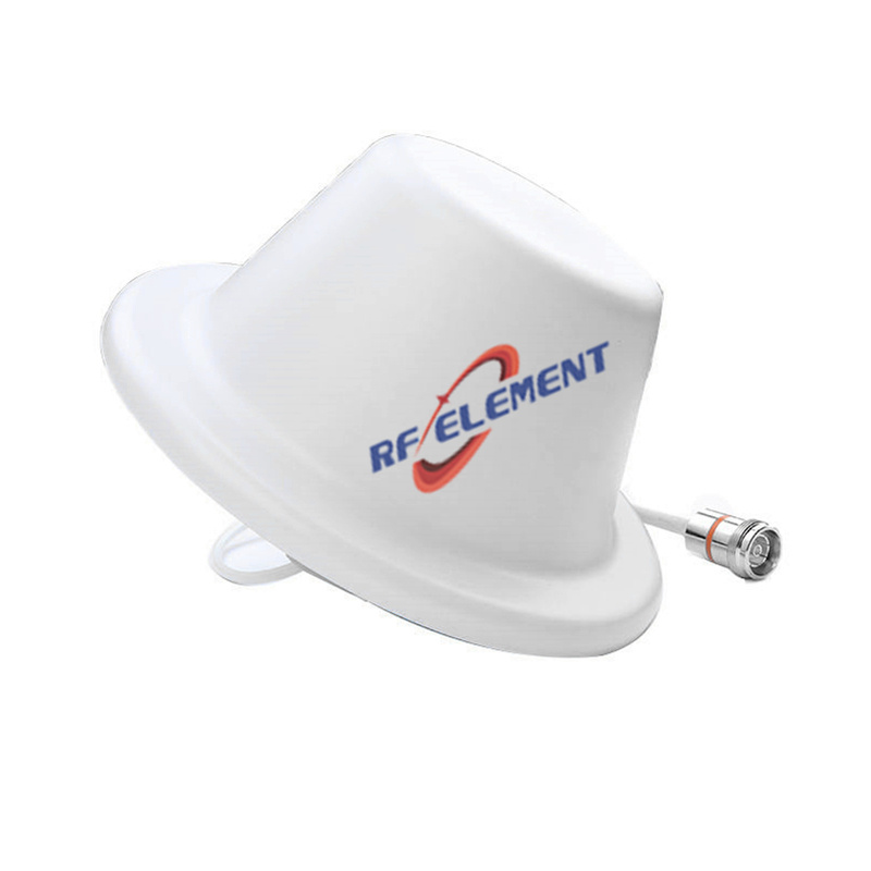
A 203 mm low PIM ceiling antenna that runs to 4000 MHz rather than stopping at 3800. The extra 200 MHz is small on paper and significant in practice: it covers the upper part of the 3.3-4.2 GHz 5G band, so a network using 3.8-4.0 GHz does not sit on the antenna's edge roll-off. Third-order PIM is -150 dBc under two 20 W carriers, and the body is 115 mm deep.
Why 4000 MHz instead of 3800
Band n77 runs 3.3-4.2 GHz and operators do not all use the same slice of it. An antenna specified to 3800 MHz works for a network centred at 3.5 GHz and starts to cost return loss for one centred at 3.9 GHz. Extending the top edge to 4000 MHz keeps the match intact across the part of the band that is actually licensed in a growing number of markets, and it does so without changing the connector or the mounting.
The price is housing depth: 115 mm, against 12-18 mm for a flat cellular disc. This unit is designed for a ceiling with a service void or for surface mounting on a concrete soffit, not for a plasterboard ceiling with no gap.
Gain and pattern
Gain is 1.5 dBi at 698-806 MHz, 2.0 dBi at 806-960 MHz, 3.0 dBi at 1710-2700 MHz and 4.0 dBi at 3300-4000 MHz. The progression is flatter than the flat discs in this range, which peak higher in the mid band; the trade is a more even behaviour across the whole span, which suits a neutral host installation where several bands carry similar traffic.
| Frequency Range | 698-4000MHz | |||
| Frequency Sub-Range(Mhz) | 698-806 | 806-960 | 1710-2700 | 3300-4000 |
| Polarization | Vertical | |||
| Gain(dBi) | 1.5 | 2.0 | 3.0 | 4.0 |
| Horizontal Beam width | 360° | |||
| Vertical Beam width | 90±10° | 85±10° | 65±10° | 40±20° |
| Impedance | 50Ω | |||
| VSWR | ≤ 1.8 | ≤ 1.5 | ≤ 1.5 | ≤ 1.8 |
| Maximum Power | 50 W | |||
| PIM, 3rd Order | -150dBc@2*43dBm | |||
| Connector | 4.3-10 Female | |||
| Dimension | φ203*115 mm | |||
| Net Weight | 0.4 kg | |||
| Packing Size | 85*36*40cm(20 PCS) | |||
| Operating Temperature | -55° to +60° C (-67° to +140° F) | |||
| Radome Material | Plastic ABS | |||
| Radome Color | White | |||
| Mounting Options | fasteners and screws included for ceiling mounting | |||
Vertical beamwidth narrows from 90 degrees at the bottom of the band to 40 degrees at the top, and horizontal coverage is 360 degrees throughout. Return loss is at or below 1.8 at 698-806 MHz, 1.5 across 806-3300 MHz and 1.8 at 3300-4000 MHz. The 1.8 at the top edge is the figure to read if the design uses 3.8-4.0 GHz heavily; it is acceptable, but it is where the match is loosest.
PIM in a shared layer
-150 dBc under two 43 dBm carriers is the operator-standard figure for an indoor passive layer, and it is met here at 115 mm depth with a single 4.3-10 Female port. Maximum power is 50 W. In a multi-operator building the antenna's own contribution sets a floor that no downstream filtering can remove, so this figure should be read together with the connector and jumper specification rather than on its own.
Installation
At 0.4 kg the unit is light, but the 115 mm body needs a clear void or a surface mount. Keep 250 mm clear of metal above the radome. Route the cable away from luminaire drivers; at 700-900 MHz those sources raise the noise floor enough to matter on a low-level uplink.
Torque the 4.3-10 to the specified value and support the cable within 150 mm of the connector. A joint that is only hand-tight passes a low-power sweep and fails PIM at operating power, which is the most common commissioning fault on indoor DAS installations.
Related units
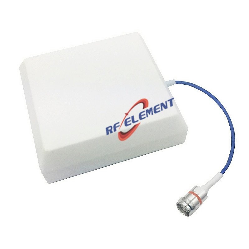
If the ceiling void is only 15 mm, the 186 mm low PIM disc covers 698-3800 MHz at the same PIM rating. If the Wi-Fi layer also needs to reach 6 GHz, the 698-6000 MHz full band unit is the one that covers it. Both are listed with the rest of the DAS in-building antenna range.
Customisation and ordering
Radome colour, cable length and packing quantity are selectable. The 203 mm diameter, 115 mm depth and 698-4000 MHz span are fixed. Samples in 3-5 days, production in 15-25 days.
Send the licensed band edges, not just the band name. A design that uses 3.8-4.0 GHz should specify this unit; one that stops at 3.8 GHz can use the flat disc and save the ceiling depth.
FAQ — 5G Indoor Antenna
What is the 5G Indoor Antenna used for?
What frequency band does the 5G Indoor Antenna cover?
What are the key specifications of the 5G Indoor Antenna?
Can RF element customize the 5G Indoor Antenna for my application?
What is the MOQ and lead time for the 5G Indoor Antenna?
How do I get a quotation for the 5G Indoor Antenna?