A low PIM antenna is normally sold on a single number: -150 dBc, sometimes -155 or -160. On its own that number means very little. Without a stated test power, intermodulation order and frequency band, it cannot be compared with a competitor's figure, and it cannot be verified on delivery. This guide explains what the rating describes, where intermodulation is actually generated inside an antenna, how the measurement is made, and how to write a specification that a supplier cannot quietly reinterpret.
What passive intermodulation is
Passive intermodulation, or PIM, is signal mixing that takes place in components that are supposed to be linear. When two or more carriers at frequencies f1 and f2 pass through a non-linear junction, new signals appear at combinations of those frequencies. The strongest products are third order, at 2f1 minus f2 and 2f2 minus f1. Fifth-order products at 3f1 minus 2f2 and 3f2 minus 2f1 are weaker but still measurable. Higher odd orders continue upward but fall away quickly.
The important property is that odd-order products land close to the original carriers, and in a frequency-division duplex system they land inside the receive band. The antenna is transmitting at full power while it is receiving at the same time. Any intermodulation it generates is therefore injected directly into its own receive path, where it behaves exactly like interference.
Every non-linearity is a potential mixer: a plated screw in the current path, an oxidized contact, a solder void, a joint between dissimilar metals, a point where two surfaces touch under insufficient pressure. PIM is not a property of the design alone. It is a property of the design, the materials and the assembly process together, which is why two antennas with identical dimensions can differ by 20 dB.
Why PIM matters more in 5G and in-building systems
In a macro site the effects are well known: raised receiver noise floor, reduced uplink sensitivity, and a coverage footprint that no longer matches the downlink. The symptom is asymmetric, which is what makes it confusing. Users see five bars and cannot upload.
Indoor distributed antenna systems concentrate the problem. A single ceiling antenna may carry several carriers from several operators at modest power each, but the aggregate power at the antenna port is high and the uplink path is short. There is little cable loss between the antenna and the receiver to absorb the interference, so a PIM level that would be tolerable on a tower becomes audible indoors. This is why DAS specifications tend to be stricter than macro specifications, and why -150 dBc at 2 x 43 dBm became the de facto indoor baseline.
5G makes the requirement harder rather than easier. Wider instantaneous bandwidth means more carriers and more combinations. Higher-order modulation is more sensitive to noise floor rise. Active antenna systems put more RF power into passive structures that were never designed as high-power components. The direction of travel is toward lower PIM, not away from it.
Reading a PIM rating: four things a number must carry
A usable PIM figure carries four pieces of information. If any one is missing, the number is marketing rather than engineering.
The first is the level in dBc. This is the intermodulation product power relative to the carrier power, measured at a defined reference plane, normally the antenna input port. -150 dBc means the product is 150 dB below the carrier at that port. Referred to a 43 dBm carrier, that is -107 dBm in absolute terms, which is far above thermal noise and entirely capable of desensitizing a receiver depending on the uplink budget between the antenna and the first amplifier.
The second is the test power. This is the single most abused parameter in datasheets. Third-order PIM falls by approximately 3 dB for every 1 dB reduction in carrier power; fifth-order falls by about 5 dB. The relationship is not exact but it is close enough to make cross-vendor comparison meaningless without it. A part quoted at -160 dBc with carriers at 2 x 37 dBm would measure about -142 dBc at 2 x 43 dBm, which is 8 dB worse than a part honestly quoted at -150 dBc with 2 x 43 dBm carriers. The apparently better number is the worse antenna. Any supplier who will not state the test power should not be shortlisted.
The third is the order. Third-order is the standard for acceptance. Fifth-order is sometimes specified for high-power or co-sited installations, and it will always read lower, so the two must never be compared directly.
The fourth is the band. PIM is frequency dependent and varies across a wideband antenna. A single spot-frequency figure taken at the most favourable point in the band is not a specification. What matters is the worst case across each operating sub-band, stated per sub-band: typically 698 to 960 MHz, 1710 to 2700 MHz and 3300 to 3800 MHz.
A fifth consideration sits behind all four: measurement uncertainty. A few dB of uncertainty is normal in PIM testing, so differences of two or three dB between two reports should be treated as noise rather than as a real performance gap.
Where PIM is generated inside an antenna
Intermodulation inside an antenna comes from a small number of physical mechanisms, and almost all of them sit in the current path rather than in the radiating aperture.
Plating and base material are the first. Tin and zinc platings are common because they are cheap and solderable, but they are also soft, prone to oxidation and, in the case of ferromagnetic substrates, mildly non-linear. Nickel underplating, widely used as a diffusion barrier, is ferromagnetic and a known PIM contributor when it sits in a high-current-density joint. Silver and copper are the low-PIM choices, provided the barrier layer and the thickness are controlled.
Joints are the second and usually the dominant one. Every screw, rivet, press fit or clamped contact in the RF current path is a potential non-linearity. The mechanism is contact resistance that varies with pressure, temperature and micro-motion. A joint that measures well on the bench can degrade after thermal cycling simply because the contact pressure relaxed. The number of joints in the current path is therefore a design variable, not a manufacturing detail.
Solder quality is the third. Voids, cold joints and flux residue all create localized non-linearity. Hand-soldered joints are the usual suspect; laser welding and controlled reflow are the usual remedy.
Surface condition is the fourth. Oxidation, contamination, moisture films and dissimilar-metal contact all raise PIM. An antenna that passes in the factory can fail six months later if the interface is not sealed.
Finally, the standard definition of the antenna under test includes more than the radiator. IEC 62037-6 defines it to include the radiating elements, the feed network, the radome and the mounting hardware, because all of them can affect the result. A metal bracket bolted to the reflector is part of the antenna as far as PIM is concerned.
Design choices that keep PIM low
The measures that work are structural rather than cosmetic, and they cost money in manufacturing rather than in material.
Reduce the number of joints in the current path. A radiator formed or stamped as a single piece, with the feed network laser-welded rather than screwed, removes most of the opportunities for intermodulation. Where joints are unavoidable, use controlled torque, thread-forming fasteners and no star washers or spring contacts in the RF path.
Choose plating for electrical reasons, not for cost. Silver over copper with a proper barrier layer is the reference solution. Where cost forces a compromise, keep the low-PIM finish at the joints and interfaces, which is where the current density is highest.
Keep the feed network symmetric. Equal path lengths and balanced power splitting reduce current crowding at transitions and make PIM behaviour more repeatable from unit to unit.
Seal the radiating assembly and provide pressure equalization. Moisture ingress is one of the most common causes of PIM that appears after installation, and it is entirely preventable with a gasket and a breather membrane.
Test in production, not only in design validation. PIM is a process-sensitive parameter: a change of plating supplier, a new solder operator or a modified fixture can move it by 10 dB. Lot sampling per IEC 62037-6, with 100 percent screening on high-value indoor units, is the only way to know that the process has not drifted. Dynamic testing, added to the 2021 edition of IEC 62037-6, is also worth requiring: it applies a defined impact energy at defined locations to expose joints that are mechanically marginal and would otherwise fail after transport or installation.
How to write a PIM specification for an RFQ
A specification that cannot be measured cannot be enforced. The following structure closes the usual loopholes.
Specify the PIM level together with the test power and the order in one sentence: third-order PIM not worse than -150 dBc with two carriers at 2 x 43 dBm. Never accept a level quoted without both.
Require the test method by standard and edition: IEC 62037-6:2021, conducted at the antenna port, in a qualified low-PIM environment, with the chamber baseline verified before the session.
State the bands separately and require the worst case in each: 698 to 960 MHz, 1710 to 2700 MHz, 3300 to 3800 MHz. Prohibit spot-frequency reporting. A wideband antenna that meets the limit at one frequency and misses it at the band edge is not compliant.
Require the result for every port and both polarizations. Multi-port antennas frequently show one port several dB worse than the others, and that port is the one that will be installed facing the coverage area.
State the acceptance regime: 100 percent test with a report per unit, or lot sampling with a defined AQL and a defined retest rule. Ask for the test report format in advance, including test power, order, sweep range, setup photograph and stated uncertainty.
Add the environmental sequence: PIM measured before and after temperature cycling between -40 and +70 degrees Celsius, damp heat at 93 percent relative humidity, and vibration. PIM that only exists on the first day is not a specification, it is a sample.
Finally, ask two questions that expose most of the gaps. Does the rating apply to the connector interface or to the complete antenna including radome and mounting hardware? And is the figure a worst case across the band, or a best-case spot value? Suppliers who answer both precisely are usually the ones whose numbers hold up.
How antenna PIM is measured
The measurement is conceptually simple and practically demanding. Two clean carriers are generated, amplified, combined and fed to the antenna under test; the intermodulation products are measured with a receiver tuned to the product frequency. The difficulty is that the test system itself generates PIM, so the whole chain, including cables, connectors, loads and the chamber, must be built and verified as a low-PIM system before any antenna is measured.
IEC 62037-1 defines the general requirements and measuring methods. IEC 62037-6 defines the fixtures and procedures specific to antennas, including radiated and conducted configurations, the definition of the antenna under test, chamber and absorber considerations, cable and connector selection, and the dynamic test added in the 2021 edition. The chamber baseline is verified with a reference low-PIM load before each session; if the baseline is not at least 10 dB better than the limit being tested, the result is not trustworthy.
In practice the carriers are swept across the band rather than parked at a single frequency, and the worst product is recorded. Both the transmit-band and receive-band products are of interest. Report the worst case, the frequency at which it occurred, and the test power.
What raises PIM after installation
Most field PIM is not caused by the antenna. It is caused by the interface, and it is diagnosable.
Connector torque is the first suspect. Under-torque leaves insufficient contact pressure; over-torque deforms the interface. Both raise PIM. Use a torque wrench and the value in the datasheet, not judgement.
Cable and jumper stress is the second. A jumper that hangs from the connector, or is bent tightly at the boot, loads the interface mechanically and changes its contact behaviour with temperature. Support the cable, respect the bend radius.
Moisture and oxidation are the third. Water in the connector, or a contaminated mating face, will raise PIM and return loss together. Any site where PIM appeared after the rainy season should be inspected at the interface first.
Loose mounting hardware is the fourth. Metal-to-metal contact that is close to the radiator, or a bracket that has worked loose, can create a non-linear path. This is why the standard includes mounting hardware in the antenna under test.
The diagnostic sequence is straightforward: measure each port separately, swap the jumper, re-torque, clean the interface, and compare. If the level follows the jumper, the antenna is innocent. If it stays with the port, the problem is internal and the unit should be replaced.
Choosing a low PIM antenna by application
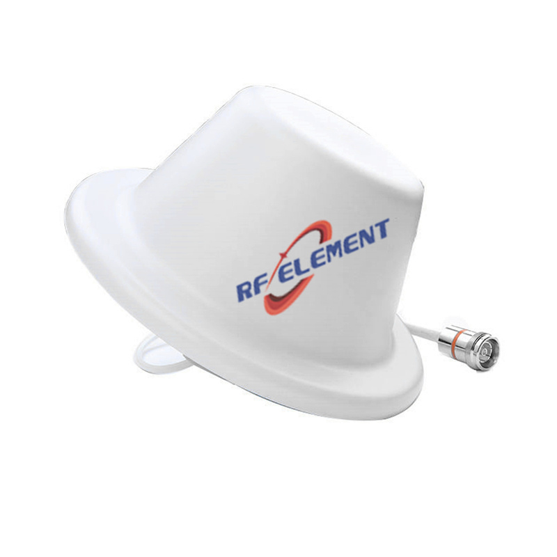
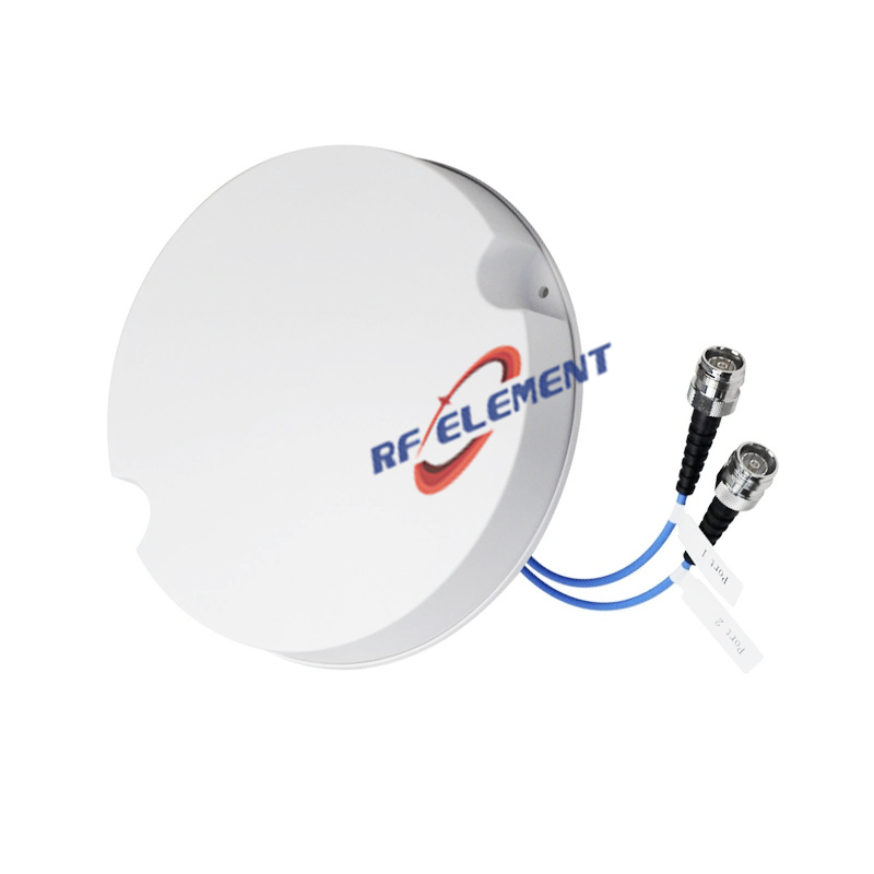
Indoor DAS ceiling coverage is the most demanding common case and the one where low PIM pays back fastest. A low-profile ceiling unit with a wideband range of 698 to 3800 MHz covers multiple operators with one part number and keeps the aggregate power at the port under control. The low PIM MIMO ceiling antenna is the typical choice where a single unit must serve several bands.
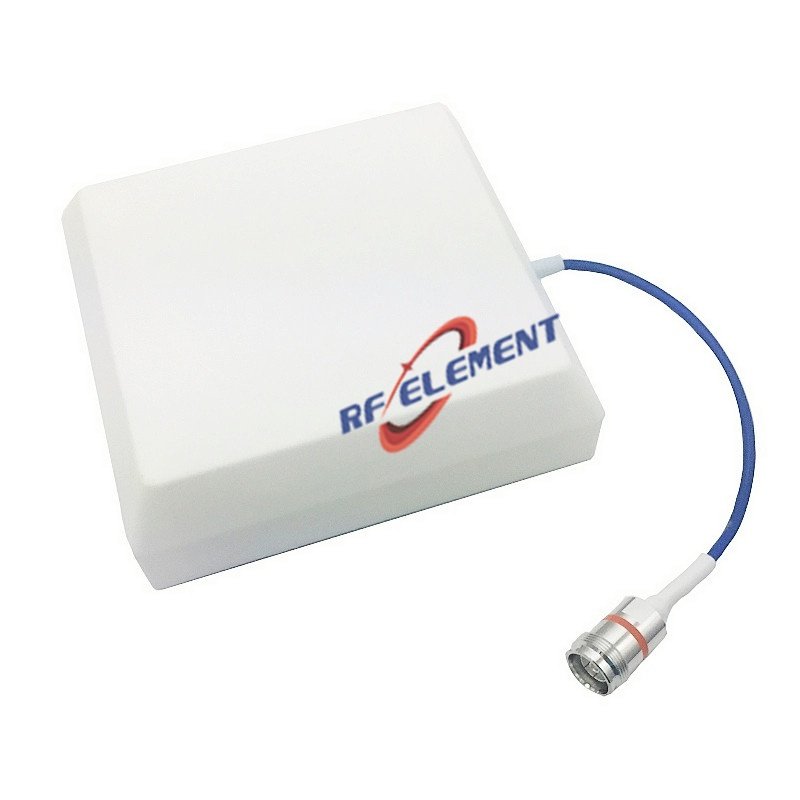
Wall-mounted indoor coverage, in corridors and stairwells, is better served by a directional panel. The low PIM MIMO panel antenna keeps the pattern facing the coverage area and reduces the power that reaches the opposite wall.
Where the ceiling void is shallow, a slim or drop-ceiling format is required, and the mechanical constraint usually comes before the RF one. The low-profile ceiling antenna exists for exactly that case.
Outdoor and industrial installations with high carrier power need the same PIM discipline plus weather sealing and mechanical robustness; the wideband low PIM panel covers the band range without a band-specific part number.
In every case the decision rule is the same: match the port count and pattern to the coverage requirement, then hold every candidate to the same specified test power and band-by-band worst case.
Frequently asked questions
Is -160 dBc better than -150 dBc?
Only if the test power and order are the same. At 2 x 37 dBm, -160 dBc corresponds to roughly -142 dBc at 2 x 43 dBm, which is worse than a genuine -150 dBc at 2 x 43 dBm. Compare at equal power or do not compare.
Can datasheet values from different vendors be compared directly?
Only when test power, order, band and method all match. In practice they rarely do, which is why the specification should dictate all four.
Does low PIM cost more?
Yes, mainly in plating, welding and testing rather than in material. The premium is small relative to the cost of a site revisit.
Does PIM affect VSWR or return loss?
No. They are independent parameters. An antenna can have excellent return loss and poor PIM, and this is common when plating or joints are the problem.
Do I need low PIM for WiFi or LoRa?
PIM matters most where a transmitter and a receiver operate simultaneously in nearby bands at high power. Single-carrier low-power systems are far less sensitive. Co-sited cellular and public-safety systems are where the requirement bites.
Can PIM be fixed on site?
If the cause is the connector, the jumper or the torque, often yes. If the level stays with the antenna port after the interface has been rebuilt, the unit must be replaced.
References
IEC 62037-1:2012, Passive RF and microwave devices, intermodulation level measurement, Part 1: General requirements and measuring methods.
IEC 62037-6:2021, Passive RF and microwave devices, intermodulation level measurement, Part 6: Measurement of passive intermodulation in antennas.
IEC 62037-3, Passive RF and microwave devices, intermodulation level measurement, Part 3: Measurement of passive intermodulation in coaxial connectors.
RF element manufactures low PIM antennas rated to -150 dBc at 2 x 43 dBm across 698 to 3800 MHz. The full range is listed on the low PIM antenna page.
TAG:What is LOW PIM antenna https://www.rfelement.com