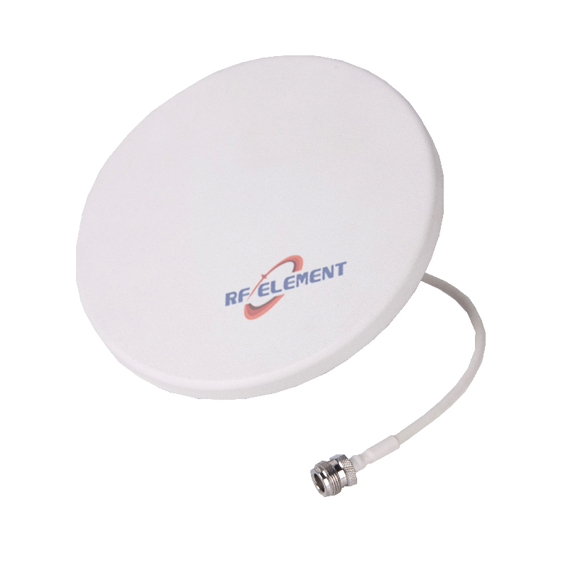
5G MIMO Ceiling Antenna | 4x4 MIMO Slim Ceiling Antenna,698-4200MHz
Upgrade your in-building wireless network with RF element's 5G 4x4 MIMO Ceiling Mounting Omni Antenna. With a wide frequency range of 698-4200MHz and low PIM performance, this high-gain omnidirectional antenna is ideal for DAS systems, enhancing 5G,4G/LTE, 3G/GSM. Easy installation and multiband design make it a versatile choice for any building. Request a quote now!
Specifications
A four-stream ceiling antenna for venues where the number of concurrent users, not the size of the floor plate, sets the requirement. The 385 x 385 mm plate carries four 4.3-10 or N-Type ports on a 13 mm deep radome, so a single ceiling position serves a 4x4 MIMO remote unit without splitting the run into two separate 2x2 drops. Coverage is 360 degrees in azimuth across 698-4200 MHz, with gain rising from 1.5 dBi in the low band to 5.5 dBi at 3.8-4.2 GHz.
When four ports earn their place
Two ports are enough for most office floors. Four ports become the cheaper option when the alternative is a second ceiling penetration, a second cable run and a second mounting position. An auditorium, a stadium concourse, a departure hall or a hospital ward corridor usually has a fixed grid of ceiling access points; adding capacity later means either pulling more cable through a finished ceiling or accepting a lower order MIMO. Specifying a 4-port plate at first fix avoids both choices.
The trade is depth and weight. At 13 mm the radome sits almost flush, but the plate is 385 mm square and 1.3 kg, which is heavier than a compact 2-port unit. Ceiling grid, drop wire and anchor selection should be checked against that figure before the layout is frozen.
Band by band behaviour
The antenna is divided into five sub-ranges because the radiating structure cannot hold one impedance and one pattern across a 6:1 bandwidth. The table below gives the measured behaviour of each sub-range rather than a single headline figure, which matters at tender stage: a carrier checking 700 MHz coverage and a neutral host checking 3.5 GHz will read different rows of the same table.
| Frequency Range | 698-4200MHz | ||||
| Frequency Sub-Range(Mhz) | 698-806 | 806-960 | 1710-2700 | 3300-3800 | 3800-4200 |
| Polarization | Vertical | ||||
| Gain(dBi) | 1.5±0.5 | 2.2±0.5 | 3.5±0.5 | 4.5±0.5 | 5.5±0.5 |
| Horizontal Beam width | 360° | ||||
| Vertical Beam width | 90±10° | 85±10° | 65±10° | 40±20° | 40±20° |
| Impedance | 50Ω | ||||
| VSWR | ≤ 1.8 | ≤ 1.5 | ≤ 1.5 | ≤ 1.5 | ≤1.8 |
| 3rd Order for 2×20 W Carriers | -153 dBc | ||||
| Isolation | ≥ 15dB | ≥ 18 dB | ≥ 12 dB | ≥ 15 dB | ≥22 dB |
| Maximum Power | 50 W | ||||
| Connector Type | 4 Port, 4.3-10 Female or N-Type Female | ||||
| Length | 385 mm | ||||
| Width | 385 mm | ||||
| Depth | 13 mm | ||||
| Net Weight | 1.3 kg | ||||
| Operating Temperature | -55° to +60° C (-67° to +140° F) | ||||
| Radome Material | Plastic ABS | ||||
| Radome Color | White | ||||
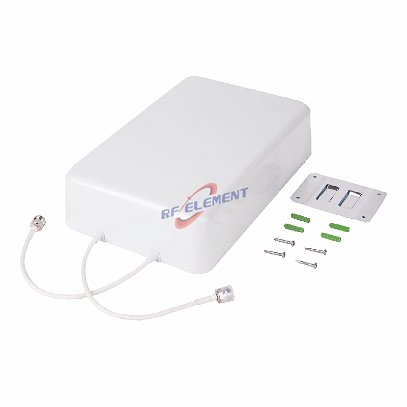
| Mounting Options | Fasteners and screws included for wall mounting | ||||
Three figures are worth reading together. The third-order PIM of -153 dBc under two 20 W carriers is the limiting specification for a shared DAS, because intermodulation generated in the antenna itself cannot be filtered downstream. Port-to-port isolation of 12 dB at 1710-2700 MHz is the lowest value in the table and sets the practical limit on how hard the two polarizations can be driven independently. Return loss stays at or below 1.5 across the middle three sub-ranges and relaxes to 1.8 at the band edges, which is normal for a structure this thin.
Ceiling practice
Keep at least 300 mm clear of metal ceiling tiles, sprinkler pipework and cable tray directly above the radome. A 360 degree pattern is easy to spoil with a steel truss 100 mm away. Where the ceiling void is shallow, the 13 mm plate is usually the only option that does not require cutting the grid.
Feed with low-loss cable sized for the longest run in the sector, not the average; a 4-port unit typically sits further from the remote unit than a 2-port one because it serves a larger zone. Torque the 4.3-10 connectors to the manufacturer's figure and weatherproof only the outdoor side of the penetration. Indoor 4.3-10 joints that are over-tightened distort the outer conductor and raise PIM.
Choosing within the range
If the floor needs 2x2 rather than 4x4, the 2-port wideband ceiling unit covers the same 698-4200 MHz span at 280 x 280 x 15 mm and 0.4 kg, which suits a standard office grid better than the 385 mm plate. Where the ceiling void is the constraint rather than the port count, the 41 mm deep 215 mm unit is easier to recess.
The four-port plate is also the right starting point for a DAS in-building deployment that has to support two operators plus a private 5G core on the same passive layer, since each operator can be given its own port pair.
Customisation and ordering
Connector type is selectable between 4.3-10 Female and N-Type Female at order. Cable length, radome colour and mounting bracket are open to specification; the frequency split, gain per sub-range and 13 mm depth are fixed by the internal structure and cannot be changed without a new tooling programme. Samples are typically available in 3-5 days and production runs in 15-25 days, with the packing quantity confirmed per order.
Send the sub-ranges you actually need to cover, the port count per ceiling position and the ceiling void depth. If the 3300-3800 MHz band is the only high band in use, we will quote against that rather than against the full 4200 MHz top end.
FAQ — 5G MIMO Ceiling Antenna
What is the 5G MIMO Ceiling Antenna used for?
What frequency band does the 5G MIMO Ceiling Antenna cover?
What are the key specifications of the 5G MIMO Ceiling Antenna?
Can RF element customize the 5G MIMO Ceiling Antenna for my application?
What is the MOQ and lead time for the 5G MIMO Ceiling Antenna?
How do I get a quotation for the 5G MIMO Ceiling Antenna?