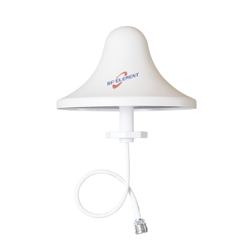
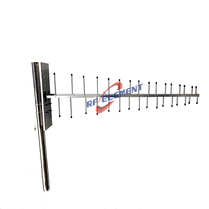
UHF Omni Antenna | Detachable UHF Omni Antenna | 450-470MHz
Specifications
A 6 dBi omni for 450-470 MHz in a 1200 mm fibreglass radome 38 mm in diameter, weighing 3.5 kg. The horizontal pattern is a full 360 degrees and the vertical beam is 35 degrees plus or minus two, VSWR is at or below 1.5, and the single port is available as N-Type female or N-Type male. It is intended for depots, ports and yards where vehicles approach from several directions.
Six decibels outdoors
At 450 MHz a 6 dBi omni is a substantial antenna, because the wavelength is 660 mm and a 1200 mm radome is less than two wavelengths long. The gain comes from stacking elements along that length, and the 35 degree vertical beam is the result.
Mounted at 15 m, the beam reaches the ground at about 47 m and extends to roughly 1.5 km with a 25 W base station and a 3 dBi mobile antenna. That footprint suits a depot, a port, a quarry or a length of road where vehicles move around a defined area rather than in one direction.
Detachable two-part radome
The antenna is supplied in two sections that join at a connector in the middle, which reduces the shipping length and allows the unit to be carried up a ladder or across a site on foot. At 3.5 kg the assembled antenna is heavy enough that the joint has to be properly seated before it is raised.
Assemble on the ground, check that the sealing ring is in place, and hand tighten only. A joint that is cross threaded or only partially engaged will show up as a VSWR rise in wet weather, and the fault will look like water ingress in the connector rather than a joint at mid-radome.
Thirty-five degree beam and site layout
The 35 degree vertical beam is narrower than the 80 degree ceiling unit and wider than a high gain 900 MHz omni. For a site where the vehicles are spread across a yard, that is a reasonable compromise: the beam does not leave a large cone of silence under the mast, and it still reaches the far fence.
If the site is very large and the vehicles are concentrated along a road, a panel aimed along the road will deliver more signal to the far end than this omni. If the site is compact and the vehicles surround the mast, the omni is the better choice.
| Frequency Range | 450-470MHz | |
| Polarization | Vertical | |
| Gain(dBi) | 6 | |
| Horizontal Beamwidth | 360° | |
| Vertical Beamwidth | 35±2° | |
| Impedance | 50Ω | |
| VSWR | ≤ 1.5 | |
| Maximum Power | 50W | |
| Connector Type | 1 Port, N-Type Female/ N-Type Male | |
| Antenna Dimension(mm) | Φ 38*1200 | |
| Net Weight | 3.5 kg | |
| Operating Temperature | -55° to +60° C (-67° to +140° F) | |
| Radome Material | Fiberglass | |
| Radome Color | White or Gray | |
| Mounting Options | Pole Mounting, 2 antenna parts for detachable installation | |
Radome, weight and wind
The 38 mm fibreglass radome is stiffer than the 20 mm tubes used on shorter UHF antennas, but a 1.2 m length still needs support above the base. Clamp at the base and at a point about 600 mm up the lower section, and keep 500 mm clearance from any metal mast: at 450 MHz that is about three quarters of a wavelength, and a closer mast will produce a deep null on one side.
The 3.5 kg weight is concentrated at the base fitting. On a pole of 40 mm or more, the load is manageable; on a thin-wall tube, use a backing plate to spread the clamping force.
Ordering
Connector gender, radome colour and packing quantity are confirmed at order. Samples in 3-5 days, production in 15-25 days.
Where the requirement is indoor coverage from a ceiling, the 3 dBi UHF ceiling antenna provides an 80 degree vertical beam at 0.5 kg. Where the site needs a directional pattern along a road or a perimeter, the UHF MIMO panel antenna delivers 9 dBi over 70 degrees.
Send the site layout, the mounting height and the radio power. On a UHF site the layout decides the antenna type, and the height decides whether the vertical beam will reach the ground where the vehicles are.
FAQ — UHF Omni Antenna
What is the UHF Omni Antenna used for?
What frequency band does the UHF Omni Antenna cover?
What are the key specifications of the UHF Omni Antenna?
Can RF element customize the UHF Omni Antenna for my application?
What is the MOQ and lead time for the UHF Omni Antenna?
How do I get a quotation for the UHF Omni Antenna?