UHF Log Periodic Antenna | 470-860MHz | 10dBi
Specifications
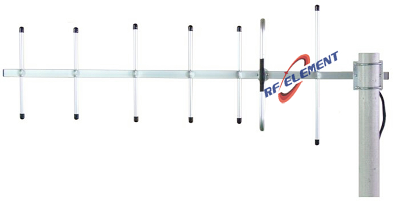
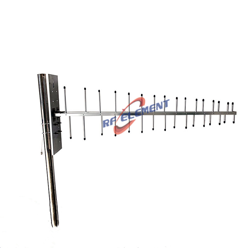
A log periodic antenna covering 470-860 MHz with 10 dBi of gain, mounted on a 1260 x 450 x 130 mm aluminium frame that weighs 1.5 kg. The horizontal beam is 70 degrees and the vertical beam 50 degrees, VSWR is at or below 1.5 across the full range, and the single port is an N-Type female connector. The element taper covers a 390 MHz span, which is why the gain is 10 dBi rather than 14.
One antenna for 390 MHz of spectrum
The difference between this antenna and the 450-470 MHz Yagi is bandwidth. A Yagi is a resonant structure cut for one band and its match falls away quickly outside it. A log periodic is a travelling wave structure: the active radiating region moves along the boom as the frequency changes, so the same antenna holds a match and a similar gain across a very wide range.
That is why the gain is 10 dBi rather than 14 dBi. A log periodic trades peak gain for bandwidth, and the 10 dBi figure is maintained across 470-860 MHz rather than achieved at one frequency and lost at the edges.
The active region and the pattern
At any given frequency, only a few elements near the front of the boom radiate effectively; the elements behind them are too long and the elements in front are too short. As the frequency rises, the active region moves toward the front of the boom, and as it falls, toward the rear. The electrical length of the antenna therefore stays constant in wavelengths, which is what keeps the pattern and the gain stable.
The practical consequence is that the phase centre moves along the boom with frequency. On a link that carries several channels at different frequencies, the apparent aiming point shifts by a few centimetres, which is negligible at this wavelength. On a direction finding or timing application, it is a specification worth knowing.
| Frequency Range | 470-860MHz | |
| Polarization | Vertical | |
| Gain(dBi) | 10 | |
| Horizontal Beamwidth | 70° | |
| Vertical Beamwidth | 50° | |
| Impedance | 50Ω | |
| VSWR | ≤ 1.5 | |
| Maximum Power | 50W | |
| Connector Type | 1 Port, N-Type Female | |
| Antenna Dimension(mm) | 1260*450*130mm | |
| Net Weight | 1.5 kg | |
| Operating Temperature | -55° to +60° C (-67° to +140° F) | |
| Material | Aluminum | |
| Radome Color | White | |
| Mounting Options | Pole mounting | |
Size, weight and mounting
At 1260 mm long, 450 mm across the longest elements and 1.5 kg, this is a substantial antenna to mount. The element span is the wind area that matters, and at 470 MHz the rear elements are long enough to flex. Clamp the boom at two points and check that the longest elements cannot touch a guy wire or a mast in wind.
The N-Type female connector is on the boom at the rear. Because the antenna covers a wide band, the feeder should be low loss across the whole range: a cable that is acceptable at 900 MHz may have 1.5 dB more loss at 470 MHz on the same length.
Where a log periodic is the right tool
It is the right antenna when the frequency is not known in advance, when several widely separated channels have to be served by one antenna, or when the installation has to cover a band that may be re-planned later. Typical uses are UHF television reception, SCADA networks that span several allocations, spectrum monitoring and public safety installations that share a mast between services.
It is the wrong tool for a single-channel link where maximum gain matters, and it is the wrong tool where the site is above 860 MHz. In both cases a Yagi or a panel is the better choice.
Ordering
N-Type female is standard, with packing quantity confirmed at order. Samples in 3-5 days, production in 15-25 days.
Where the requirement is confined to 450-470 MHz and a higher gain is wanted, the 450-470 MHz UHF Yagi antenna is smaller and better matched within its band. Where the link is at 900 MHz and the frequency is fixed, the 14 dBi 900 MHz GSM Yagi antenna delivers 4 dB more gain in a similar boom length.
Send the frequency plan, the number of channels and the mounting height. A log periodic is specified by the band it has to cover, not by a single centre frequency.
FAQ — UHF Log Periodic Antenna
What is the UHF Log Periodic Antenna used for?
What frequency band does the UHF Log Periodic Antenna cover?
What are the key specifications of the UHF Log Periodic Antenna?
Can RF element customize the UHF Log Periodic Antenna for my application?
What is the MOQ and lead time for the UHF Log Periodic Antenna?
How do I get a quotation for the UHF Log Periodic Antenna?