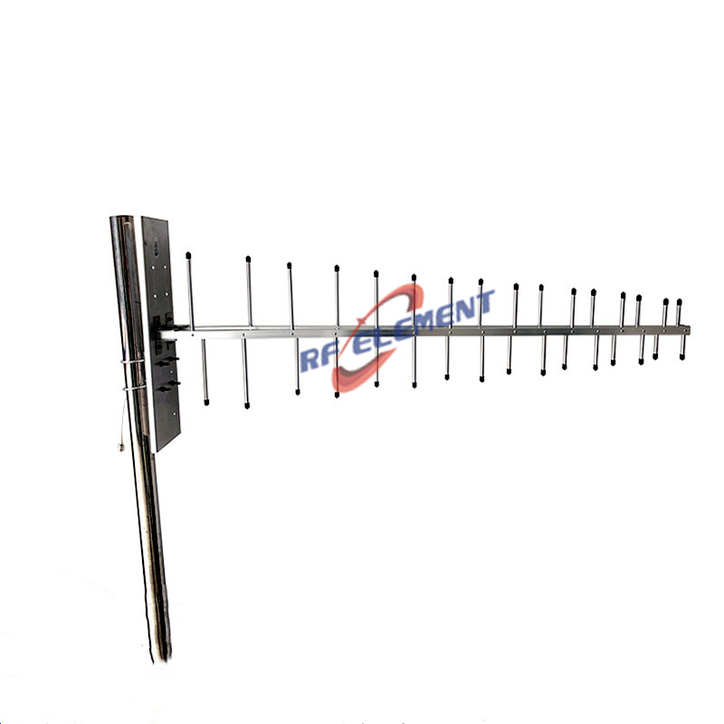
VHF Omni Antenna | UHF Omni Antenna | 150-860MHz
- Supported Frequencies: 150-860MHz
- Gain: >-5dBi to 4 dBi
- VSWR: <2.5
- Polarization: Vertical
- Antenna Size: φ360*15cm
Specifications
This VHF UHF omni antenna covers 150-860MHz in a single 360 degree radiator, with gain from -5dBi at the low end to 4-5dBi across 450-860MHz, 100W of continuous power handling and a 15cm profile. It is built for mixed indoor and outdoor deployments where one antenna model has to serve public safety radio, maritime communications and agricultural IoT links without a band-specific variant for each.
One antenna across 150-860MHz
A 5.7:1 bandwidth ratio is where the engineering difficulty lives. At 150MHz a quarter-wave monopole alone is about half a metre tall, so a conventional design that holds gain across the band becomes a mast rather than an antenna. At the same time the impedance match has to stay stable through 300MHz and 600MHz, where a simple wideband structure tends to produce VSWR peaks.
The alternative to a large radiator is a smaller one with a matching network that does the work. Our design uses a tapered helical radiator combined with a lumped-distributed impedance network, so the transition from the low end to the high end is spread across the band instead of concentrated at a few points.
Radiator and matching network
Folded helical elements let the radiator fit a much shorter height than a straight monopole while keeping an omnidirectional pattern. The ground-plane-independent structure means the antenna does not depend on a large metal surface beneath it to work, which is what allows the same unit to be ceiling-mounted indoors and pole-mounted outdoors without a different earth reference.
The matching network combines lumped components with distributed transmission-line sections. Lumped elements handle the low-frequency correction in a small space, while the distributed sections keep losses low at the high end where a purely lumped network would become impractical. The result is a VSWR below 2.5 across the full span, which is the figure to use for link budgeting at the band edges.
The radome is fiberglass with a UV-resistant coating rated to IP67, and the base is a corrosion-resistant aluminum alloy, so the same antenna survives a coastal installation and an indoor ceiling without a separate outdoor variant.
Specifications
| Parameter | Value |
|---|---|
| Frequency range | 150-860MHz |
| Gain 150-165MHz | -5 to 4dBi |
| Gain 450-860MHz | 4-5dBi |
| VSWR | <2.5 across the band |
| Polarization | Vertical |
| Power handling | 100W continuous |
| Dimensions | Φ360 x 15cm |
| Radome | Fiberglass, UV-resistant coating, IP67 |
| Base | Corrosion-resistant aluminum alloy |
Indoor and outdoor use
Indoors, the low profile and the ground-plane-independent design allow ceiling mounting in command rooms and equipment halls without a visible mast. Coverage through 500-800MHz is what makes a single unit practical where handheld radios and UHF repeaters share the same space. Outdoors, the same antenna pole-mounts on vehicles or masts and handles the temperature swing of a coastal or desert site.
Do not expect the 150MHz figure to behave like the 450MHz figure. At the bottom of the band the antenna is electrically small and the pattern is broader with lower gain, so a link plan that works at 450MHz should be recalculated rather than scaled when the same site also uses 150-174MHz.
Deployment notes
Mount the antenna as high as practical and keep it away from metal masts and roof structures, because the low-frequency pattern is the first to be disturbed by nearby conductors. Use a feeder rated for the highest frequency in use and keep the run as short as the layout allows, since the 860MHz end loses more per metre than the 150MHz end. Provide a ground path and a surge arrester for outdoor installations, and seal the connector against moisture even when the antenna is rated IP67.
Customization and ordering
Band coverage, gain distribution and connector type can be adjusted, and a sub-band version tuned for 150-174MHz or 450-470MHz is available where the full span is not needed. The mounting base can be supplied for ceiling, wall or pole attachment, and the radome colour can be changed for architectural installations.
Send the band plan, mounting environment, power level and quantity to sales@rfelement.com. Samples are typically ready in 3-5 working days and mass production in 15-25 working days.
FAQ — VHF Omni Antenna
What is the VHF Omni Antenna used for?
What frequency band does the VHF Omni Antenna cover?
What are the key specifications of the VHF Omni Antenna?
Can RF element customize the VHF Omni Antenna for my application?
What is the MOQ and lead time for the VHF Omni Antenna?
How do I get a quotation for the VHF Omni Antenna?