UHF Ceiling Antenna | 450-470MHz Ceiling Antenna | 3dBi
Specifications
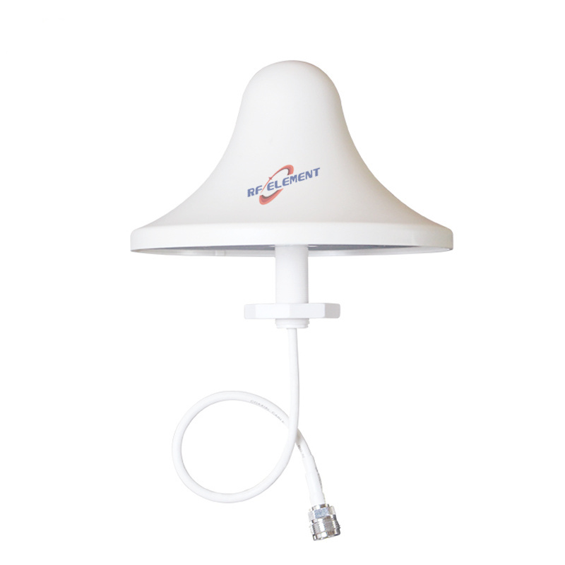
A low profile ceiling antenna for 450-470 MHz indoor coverage, 166 mm in diameter and 98 mm deep, weighing 0.5 kg. The horizontal pattern is a full 360 degrees and the vertical beam is 80 degrees, VSWR is at or below 1.5, and the single port is an N-Type female connector. It is intended for rooms and plant areas where handheld radios move around the space.
Eighty degrees fills a room
An 80 degree vertical beam is almost a hemisphere in front of the antenna. Ceiling mounted at 3 m, it reaches the floor about 1.8 m from the point below and covers a room of roughly 12 m across with no gap at the walls. That is the pattern a two-way radio system needs indoors, where handhelds move around a space rather than sitting in one direction.
The 3 dBi gain is low, and deliberately so. At 450 MHz a higher gain ceiling antenna would narrow the vertical beam and leave the corners of the room in shadow. The gain figure is not the specification that matters here; the 80 degree beam is.
| Frequency Range | 450-470MHz | |
| Polarization | Vertical | |
| Gain(dBi) | 3 | |
| Horizontal Beamwidth | 360° | |
| Vertical Beamwidth | 80° | |
| Impedance | 50Ω | |
| VSWR | ≤ 1.5 | |
| Maximum Power | 50W | |
| Connector Type | 1 Port, N-Type Female | |
| Antenna Dimension(mm) | Φ166*98 | |
| Net Weight | 0.5 kg | |
| Operating Temperature | -55° to +60° C (-67° to +140° F) | |
| Radome Material | ABS | |
| Radome Color | White | |
| Mounting Options | Fasteners and screws included for wall mounting | |
Ninety-eight millimetres deep
The 98 mm depth is the radome plus the ground plane. On a suspended ceiling the antenna sits below the tile line, which is visible but manageable; on a concrete ceiling it projects far enough to be a head clearance issue in a low plant room.
For a low ceiling, the alternative is a wall-mounted panel aimed across the space. The ceiling unit is easier to position and gives a more even pattern, so it remains the default for rooms above about 2.7 m.
450-470 MHz and the services inside it
The band covers the UHF business band and the GMRS and FRS two-way services in the United States, along with a number of public safety allocations in other countries. The antenna is passive and works with any radio in that range; the specification that matters is the band edges rather than the service name.
The 20 MHz span allows a well matched design with VSWR at or below 1.5 across the whole band, which is why this antenna should not be used outside 450-470 MHz. At 430 MHz the match degrades, and at 480 MHz the pattern shifts in elevation.
Installation and cable
Fasteners and screws for wall or ceiling mounting are included. The N-Type female connector faces the ceiling void, so the cable must be routed above the tile line and a service loop left for maintenance. At 450 MHz the loss of thin coax is significant: 10 m of RG58 costs about 2 dB, which is two thirds of the antenna gain.
Where the cable run is long, use a low loss feeder and consider mounting the radio closer to the antenna. At this frequency the cable is often the largest single loss in the system, not the antenna.
Ordering
N-Type female is standard, with radome colour and packing quantity confirmed at order. Samples in 3-5 days, production in 15-25 days.
Where the coverage area is larger than a single room, the 6 dBi UHF omni antenna uses a 1200 mm radome for outdoor and large indoor spaces. Where the space is long and narrow, the UHF MIMO panel antenna provides 9 dBi with a 70 degree beam.
Send the room dimensions, the ceiling height and the radio power. At 450 MHz the ceiling height and the cable run decide the coverage more than the antenna gain does.
FAQ — UHF Ceiling Antenna
What is the UHF Ceiling Antenna used for?
What frequency band does the UHF Ceiling Antenna cover?
What are the key specifications of the UHF Ceiling Antenna?
Can RF element customize the UHF Ceiling Antenna for my application?
What is the MOQ and lead time for the UHF Ceiling Antenna?
How do I get a quotation for the UHF Ceiling Antenna?