UHF MIMO Panel Antenna | Dual Polarity UHF Panel Antenna | 450-470MHz
Specifications
A 9 dBi dual-polarised panel for 450-470 MHz on a 450 x 450 x 40 mm plate weighing 3.0 kg. The horizontal beam is 70 degrees and the vertical beam 65 degrees, VSWR is at or below 1.5, and the two ports are N-Type female on a horizontal and vertical lattice. It is intended for sites that need polarisation diversity as much as raw gain.
MIMO at 450 MHz is a different problem
At 2.4 GHz a second spatial stream is easy to realise because the wavelength is short and the environment is rich in scattering. At 450 MHz the wavelength is 660 mm, buildings and vehicles are comparable in size to the wavelength, and the number of independent paths is smaller. A 2x2 branch at this frequency still helps, but the gain is more modest and more dependent on the environment.
What the second polarisation does reliably at 450 MHz is provide polarisation diversity. A handheld radio in a building may be vertical or tilted, and two orthogonal receive branches reduce the depth of the fades that a single vertical antenna would experience. That is a more dependable benefit than the theoretical doubling of throughput.
Seventy degrees covers a yard or a road
At 70 degrees the beam covers about 140 m of width at 100 m and 700 m at 500 m. For a public safety or business radio site serving a depot, a campus or a length of road, that is a sensible compromise between reach and breadth.
The 65 degree vertical beam is almost as wide, so the panel does not need careful downtilt. Mounted at 12 m, coverage begins about 10 m in front of the plate and continues to the radio horizon on a clear path. That suits a wall or a gantry position overlooking the area.
| Frequency Range | 450-470MHz | |
| Polarization | Horizontal+Vertical | |
| Gain(dBi) | 9 | |
| Horizontal Beamwidth | 70° | |
| Vertical Beamwidth | 65° | |
| Impedance | 50Ω | |
| VSWR | ≤ 1.5 | |
| Maximum Power | 50W | |
| Connector Type | 2 Port, N-Type Female | |
| Antenna Dimension(mm) | 450*450*40 | |
| Net Weight | 3.0 kg | |
| Operating Temperature | -55° to +60° C (-67° to +140° F) | |
| Radome Material | ABS | |
| Radome Color | White | |
| Mounting Options | Pole Mounting | |
450 mm and 3 kg at UHF
A 450 mm plate at 450 MHz is about two thirds of a wavelength across, which is why the gain is 9 dBi rather than the 18 dBi that the same size would give at 2.4 GHz. The 3.0 kg weight is the plate, the reflector and the dual-polarised feed structure, and it requires a pole of 50 mm or more with both fixing points used.
The 40 mm depth keeps the centre of pressure close to the mounting surface, but the 450 mm square face is still a wind sail. On an exposed roof, check the bracket rating rather than relying on the antenna weight alone.
Ports, feeders and isolation
Two N-Type female ports require two feeders from the radio. At 450 MHz the loss of a long feeder is high, so keeping the radio close to the antenna is more valuable than at higher frequencies. If the two feeders differ in length by more than a few metres, the phase imbalance between branches will reduce the diversity benefit.
Isolation between the ports is not stated in the table. For a diversity receiver this is rarely the limiting factor, but where the two ports feed separate transmitters on the same band, ask for the isolation at the operating frequency before committing.
Ordering
Two N-Type female ports are standard, with radome colour and packing quantity confirmed at order. Samples in 3-5 days, production in 15-25 days.
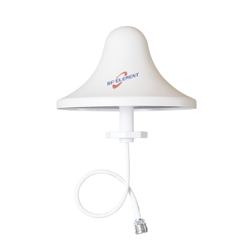
Where the requirement is a full circle rather than a direction, the 6 dBi UHF omni antenna covers 450-470 MHz in a 1200 mm radome. Where the space is indoors and the ceiling is the mounting surface, the 3 dBi UHF ceiling antenna provides an 80 degree vertical beam at 0.5 kg.
Send the radio port configuration, the area to be covered and the mounting height. The port configuration decides whether the second branch is used for diversity or for a second carrier, and that changes the isolation requirement.
FAQ — UHF MIMO Panel Antenna
What is the UHF MIMO Panel Antenna used for?
What frequency band does the UHF MIMO Panel Antenna cover?
What are the key specifications of the UHF MIMO Panel Antenna?
Can RF element customize the UHF MIMO Panel Antenna for my application?
What is the MOQ and lead time for the UHF MIMO Panel Antenna?
How do I get a quotation for the UHF MIMO Panel Antenna?