5G External Antenna | 11dBi Log Periodic LPDA for Outdoor 5G
This rugged 5G external antenna delivers 11dBi gain across 698-4200MHz. Perfect for outdoor DAS, 4G/5G signal boosters & point-to-point links. Get a quick quote today!
Specifications
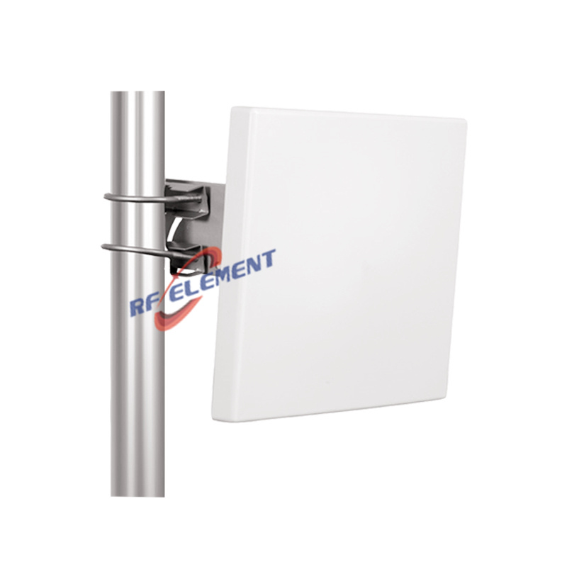
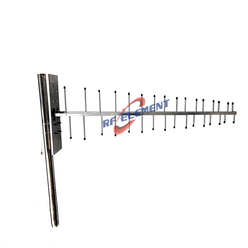
A log periodic dipole array for 698 to 4200 MHz in a 442 by 210 by 65 mm ABS housing, with 9 dBi at the bottom of the band rising to 12 dBi at the top. Polarization is vertical, the beam narrows from 70 degrees horizontal at 698 MHz to 50 degrees at 4 GHz, and the single port is a 4.3-10 or N-Type female rated at 50 W. VSWR is 1.5 or better across 698 to 960 MHz and 1.8 or better above that. The unit weighs 1.2 kg and mounts on a pole.
A 442 mm boom on a 430 mm wave
At 698 MHz the free space wavelength is 430 mm, so the boom is just over one wavelength long. At 3900 MHz the wavelength is 77 mm and the same boom is 5.7 wavelengths. A log periodic antenna scales its gain with the number of active elements, and the number of active elements is set by how many wavelengths of boom the frequency sees.
That is why the gain is not flat. It climbs from 9 dBi to 12 dBi across the band because the boom is electrically longer at the top end. A manufacturer cannot flatten that curve without adding length, and this is the longest boom in the two version range for exactly that reason.
Why the 3 dB difference at the bottom matters most
Against the 285 mm version of the same antenna, this one is 3 dB stronger at 698 to 806 MHz, 2.5 dB at 806 to 960 MHz, 2 dB at 1710 to 2700 MHz and 1.5 dB at 3800 to 4200 MHz. The gap is widest where the wavelength is longest, which is the physics described above.
Most 5G deployments care about the bottom of that table. Band n28 sits at 700 MHz, band n8 and the legacy 900 MHz services sit just above it, and both are coverage bands where 3 dB is the difference between a cell edge that works and one that does not. If the site plan includes any 700 or 800 MHz carrier, this is the version to order, and the extra 157 mm of boom is the cheapest 3 dB in the catalogue.
Two match zones, not one
VSWR is 1.5 or better from 698 to 960 MHz and 1.8 or better from 1710 to 4200 MHz. The 1.5 figure is a return loss of 14 dB and a mismatch loss of 0.18 dB, while 1.8 is 10.9 dB and 0.37 dB. Neither number is a problem in a link with normal margin, but the step tells a planner where the matching network was optimised.
It is worth comparing this with the shorter version, which holds 1.5 all the way to 2700 MHz. The long boom buys low band gain and pays for it with a slightly looser match in the middle of the band. If the deployment is 1710 to 2700 MHz only, the shorter antenna is the better match and the gain difference at those frequencies is only 2 dB.
| Frequency Range | 698-4200MHz | ||||
| Frequency Sub-Range(Mhz) | 698-806 | 806-960 | 1710-2700 | 3300-3800 | 3800-4200 |
| Polarization | Vertical | ||||
| Gain(dBi) | 9±0.5 | 9.5±0.5 | 11±0.5 | 11.5±0.5 | 12±0.5 |
| Horizontal Beam width | 70±10° | 65±10° | 60±10° | 55±10° | 50±10° |
| Vertical Beam width | 55±10° | 55±10° | 50±10° | 45±20° | 40±10° |
| Impedance | 50Ω | ||||
| VSWR | ≤ 1.5 | ≤ 1.5 | ≤ 1.8 | ≤1.8 | ≤1.8 |
| Maximum Power | 50 W | ||||
| Connector Type | 1 Port, 4.3-10 Female or N-Type Female | ||||
| Length | 442 mm | ||||
| Width | 210 mm | ||||
| Depth | 65 mm | ||||
| Net Weight | 1.2 kg | ||||
| Operating Temperature | -55° to +60° C (-67° to +140° F) | ||||
| Radome Material | Plastic ABS | ||||
| Radome Color | White | ||||
| Mounting Options | Pole mounting | ||||
1.2 kg and 0.09 square metres
The projected area is 442 by 210 mm, about 0.09 square metres. At 30 m per second that is roughly 60 N of drag with a coefficient of 1.2, so a 40 mm pole and a single clamp are enough. The housing is sealed ABS with a white finish, which keeps the solar load down on a south facing wall.
The 65 mm depth matters on a narrow ledge. A log periodic needs no reflector, so it can sit 65 mm off the mounting surface where a panel or a Yagi of the same gain would need several times that depth behind it.
Ordering
The connector is 4.3-10 female or N-Type female, polarization is vertical, and the bracket suits a 40 to 50 mm pole. Samples in 3-5 days, production in 15-25 days.
For a site where the lowest carrier is above 1710 MHz, the 285 mm LPDA version weighs 0.8 kg and holds a 1.5 match across the whole middle band. For a point to point link that needs more than 12 dBi, the 5G MIMO feedhorn turns a 60 cm dish into a 23 to 28 dBi link. The rest of the range is listed under 5G antenna.
Send the band plan, the mounting surface and the required gain at the lowest carrier. The band plan decides the boom length, the surface decides the bracket, and the low band gain requirement is the one figure that the two versions do not share.
FAQ — 5G External Antenna
What is the 5G External Antenna used for?
What frequency band does the 5G External Antenna cover?
What are the key specifications of the 5G External Antenna?
Can RF element customize the 5G External Antenna for my application?
What is the MOQ and lead time for the 5G External Antenna?
How do I get a quotation for the 5G External Antenna?