Full Bands Anti-Drone Omni Antenna
Specifications
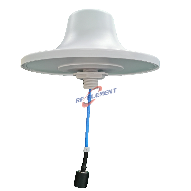
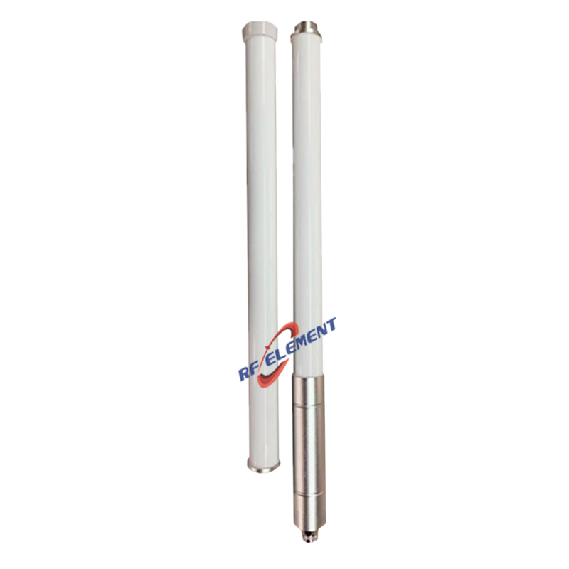
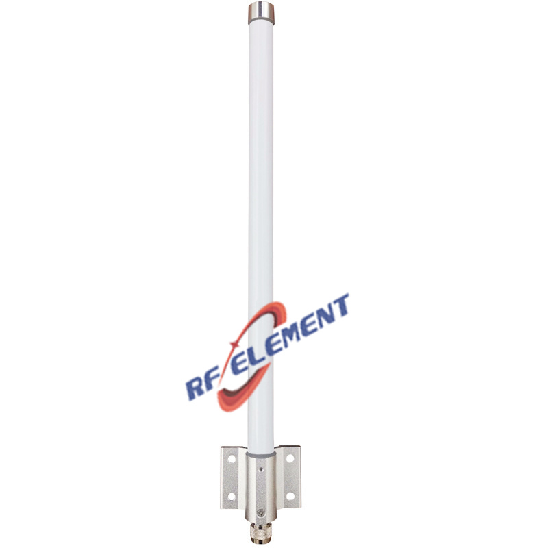
This full-band anti-drone omni antenna covers 433MHz through 5.8GHz, including the 1.2GHz, 1227.60MHz and 1575.42MHz navigation bands, and handles more than 300W of input power. It is built as four 90 degree sector antennas that together form a 360 degree ring, so a counter-UAS site gets broad frequency coverage, directional gain and high power handling in one compact installation.
Why the band list looks like this
The frequency plan follows the links a UAV actually uses, not a generic wideband sweep. Control and telemetry links sit in the 433MHz, 868MHz, 915MHz and 2.4GHz bands. Video downlinks concentrate around 2.4GHz and 5.8GHz. The 1227.60MHz and 1575.42MHz entries are the GNSS L2 and L1 carriers, which matter because a counter-UAS system often needs to detect or deny position fixes rather than only break a control link. The 1.2GHz entry covers the video and telemetry links used by several long-range platforms.
Covering all of these in one antenna is not the same as covering them well. A single wideband omni that spans 433MHz to 5.8GHz would have modest gain at every frequency, and gain is exactly what a detection or mitigation chain needs at range.
Four sectors instead of one omni
We divided the design into four identical full-band sector antennas, each with a 90 degree horizontal beamwidth. Combined on a single mast, the four sectors cover 360 degrees with no mechanical rotation and no single point of coverage loss. Each sector carries the entire band list, so the array does not need separate antennas per frequency and the site keeps a uniform appearance.
Sectorization also raises usable gain. Energy that would be spread around a full circle is concentrated into a quarter of it, which improves the link budget in every direction while keeping the 360 degree coverage that a counter-UAS site requires. The trade-off is that sector boundaries must be planned: with four overlapping 90 degree patterns, the crossover points determine how much ripple the detection system sees as a target crosses the site.
Power handling and thermal behaviour
More than 300W of input power puts the antenna in a different category from a receive-only monitoring unit. The feed network, the radiator joints and the housing all have to dissipate heat without changing dimensions, because thermal expansion at these tolerances shifts the impedance match. Materials and component selection were driven by that requirement as much as by bandwidth, and the assembled antenna was tuned across all bands before release rather than band by band.
Specifications
| Parameter | Value |
|---|---|
| Frequency bands | 433MHz, 868MHz, 915MHz, 1.2GHz, 1227.60MHz, 1575.42MHz, 2.4GHz (2400-2500MHz), 5GHz (5150-5850MHz) |
| Gain | 5-20dBi |
| VSWR | <2.0 |
| Polarization | Vertical |
| Power handling | >300W |
| Configuration | 4 x 90° sectors, 360° combined |
| Form factor | Compact omni housing |
Deployment notes
Mount the array as high as the site allows and keep it clear of nearby metalwork, because a 433MHz element sees a much larger near field than a 5.8GHz one and detuning from a mast or a rooftop parapet shows up first at the low end. Provide a direct ground path and a surge arrester on each feeder, since these installations are usually the tallest structure on a site. Use low-loss cable rated to 6GHz and keep runs equal in length where the system compares phase between sectors.
Vertical polarization is the right default for UAV links, but the installer should confirm the polarization of the target links in the area of operation. A cross-polarized control signal can cost more link budget than the antenna gain provides.
Customization and ordering
Band sets, sector count, gain distribution and connector type can be adapted to the detection or mitigation equipment a site already runs. Housing colour, mounting hardware and port labelling can be changed for OEM programmes, and a narrower band set is available where the full list is not required.
Send the required bands, power level, sector configuration and quantity to sales@rfelement.com. Samples are typically ready in 3-5 working days and mass production in 15-25 working days.
FAQ — Full Bands Anti-Drone Omni Antenna
What is the Full Bands Anti-Drone Omni Antenna used for?
What frequency band does the Full Bands Anti-Drone Omni Antenna cover?
What are the key specifications of the Full Bands Anti-Drone Omni Antenna?
Can RF element customize the Full Bands Anti-Drone Omni Antenna for my application?
What is the MOQ and lead time for the Full Bands Anti-Drone Omni Antenna?
How do I get a quotation for the Full Bands Anti-Drone Omni Antenna?