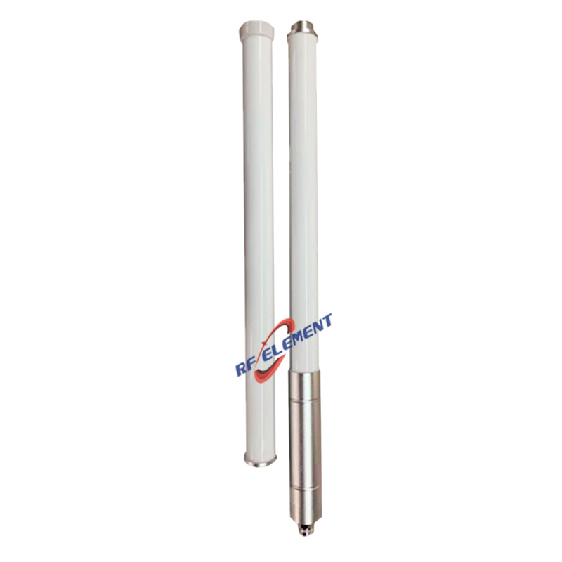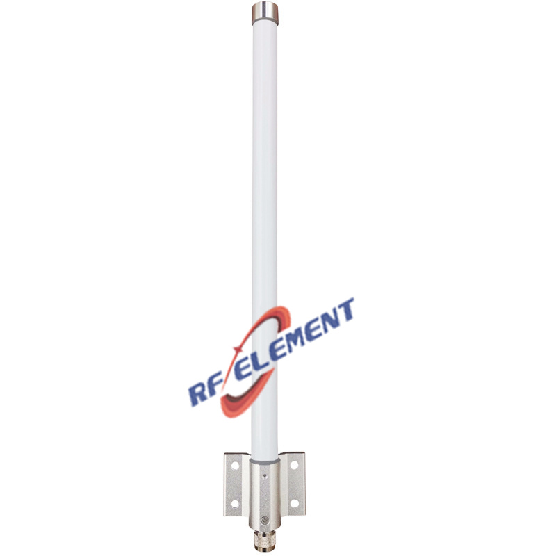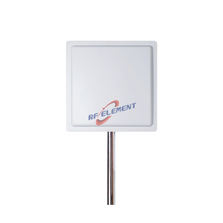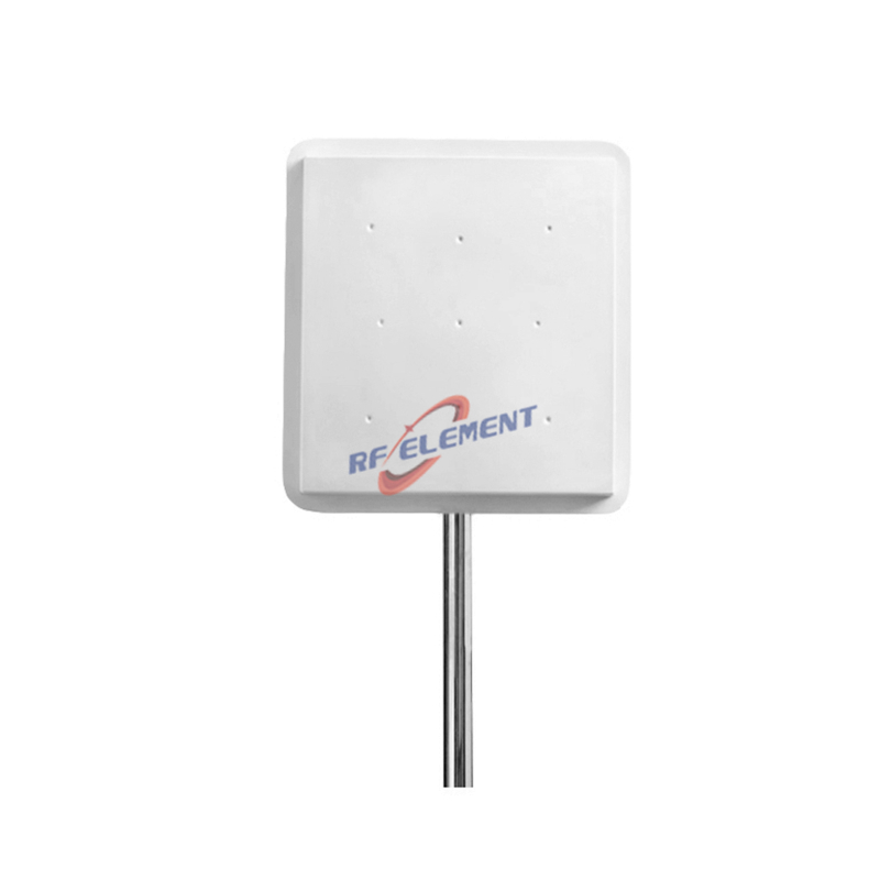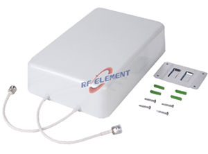
Multi-Bands Anti Drone Antenna | 433MHz,915MHz,1575MHz, 2445MHz,5850MHz
- Supported Frequencies: 433MHz, 915MHz, 1575MHz, 2445MHz, 5850MHz
- Gain: from 2dBi to 8dBi
- VSWR: <1.8
- Polarization: vertical
Specifications
This multi-band anti-drone antenna covers 433MHz, 915MHz, 1575MHz, 2445MHz and 5850MHz from an octagonal housing with separate SMA ports, giving a counter-UAS installation five functional bands in one compact unit. Gain runs from 2dBi to 8dBi depending on the band, and the housing is small enough to sit discreetly on a mast beside the equipment it serves.
Five bands grouped by function
The band list is not arbitrary; it maps onto how a UAV stays connected. The 433MHz and 915MHz entries cover the long-range control and telemetry links used by many commercial and modified platforms. The 1575.42MHz entry is the GPS L1 carrier, which a detection system may monitor to identify a platform holding a position fix. The 2445MHz and 5850MHz entries cover the 2.4GHz and 5.8GHz video and control links that most consumer drones rely on for short-range operation.
Grouping the bands this way lets the site use one antenna for several receivers instead of stacking a separate whip for each frequency. It also means the band that matters most can be given more of the aperture, which is why gain is not uniform across the five entries.
Octagonal reflector and port layout
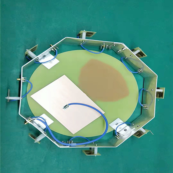
The octagonal shape is functional rather than decorative. Eight aluminum reflector panels around the radiator set up a controlled reflective structure that raises gain in the horizontal plane while keeping the package compact. Inside that structure, the 2.4GHz and 5.8GHz elements are carried on a dual-band circuit board at the top of the antenna, which is the position least affected by the reflector panels and keeps coupling between the two high bands low.
The 433MHz, 915MHz and 1575MHz circuit boards are distributed around the reflector body at even spacing. Spreading them out rather than stacking them in one place reduces mutual coupling between the low bands, where the elements are physically longest and most likely to interact. Each band ends in its own SMA port, so the receiver or mitigation equipment can be connected band by band and the site is not forced into a single combined feed.
Specifications
| Parameter | Value |
|---|---|
| Frequency bands | 433MHz, 915MHz, 1575MHz, 2445MHz, 5850MHz |
| Gain | 2-8dBi |
| VSWR | <1.8 |
| Polarization | Vertical |
| Connector | SMA, one port per band |
| Housing | Octagonal, aluminum reflector body |
Installation
Mount the unit vertically, clear of large metal surfaces, and keep the SMA pigtails short and equal in length where the system compares phase across bands. Use a torque wrench on the SMA connectors; the small thread size makes it easy to over-tighten and crack the dielectric, which shows up as a VSWR drift that appears only after a few weeks outdoors. Provide a ground path from the mast and protect the ports with self-amalgamating tape if the enclosure is not sheltered.
Because the low-band elements see a wider aperture than the high-band ones, check the 433MHz channel after mounting rather than relying on the factory sweep. A nearby mast arm or roof edge can shift the low-band pattern without visibly affecting 2.4GHz or 5.8GHz.
Customization and ordering
Band sets, port count, connector type and housing finish can be adapted to an existing detection or mitigation platform. A four-band version without the GNSS element is available where position monitoring is handled by a separate antenna, and OEM labelling and packaging can be applied.
Send the required bands, port count, connector type and quantity to sales@rfelement.com. Samples are typically ready in 3-5 working days and mass production in 15-25 working days.
FAQ — Multi-Bands Anti Drone Antenna
What is the Multi-Bands Anti Drone Antenna used for?
What frequency band does the Multi-Bands Anti Drone Antenna cover?
What are the key specifications of the Multi-Bands Anti Drone Antenna?
Can RF element customize the Multi-Bands Anti Drone Antenna for my application?
What is the MOQ and lead time for the Multi-Bands Anti Drone Antenna?
How do I get a quotation for the Multi-Bands Anti Drone Antenna?