Where and How to Mount a LoRa Antenna for Maximum Range
LoRa antenna range is decided by placement before it is decided by gain. A well-chosen antenna mounted badly will lose to a modest antenna mounted well, and the difference is rarely a fine margin: a gateway antenna tucked into a plant room behind two concrete walls can lose 20 dB or more, which is the same as shortening every link in the network by a factor of ten. This guide walks through the mounting decisions that set LoRa antenna range in practice, for both 868 MHz and 915 MHz networks, and ends with a short checklist you can run before ordering hardware.
Height first: line of sight beats every other specification
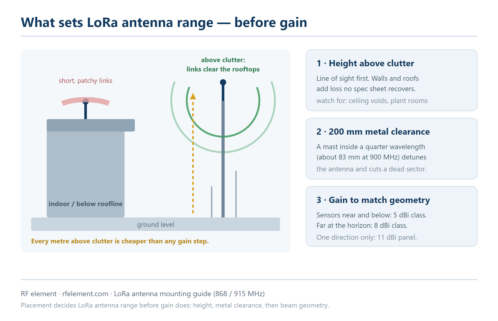
At 900 MHz, distance is won or lost in the last few metres around the antenna. Radio waves at sub-GHz frequencies diffract around obstacles better than Wi-Fi does, but every wall, slab and stacked pallet between the antenna and the sensor adds loss that no specification sheet can recover. The cheapest gain in a LoRa network is almost always vertical: moving the gateway antenna from inside a ceiling void to a pole on the roof changes the link budget far more than swapping a 5 dBi antenna for an 8 dBi one.
A practical target is to get the antenna above the tallest local clutter: above the roofline in an urban street, above crop height on a farm, above the stack height in a yard. Each metre of height is worth more where the terrain is flat, because the radio path stops grazing rooftops and starts clearing them. You do not need an engineering survey to see this — the network itself tells you. If packet reception improves noticeably whenever it rains (wet foliage loss disappears when leaves are absent) or at night (less vehicle clutter), the antenna is buried in clutter and height is the fix.
Omnidirectional or directional: match the antenna to the gateway's job
Once the antenna is up where it can see the world, the choice between omnidirectional and directional comes down to what the gateway is actually doing:
Gateway in the middle of the sensor field — nodes spread all around it. An omnidirectional antenna is the right answer, and the gain question is how tight the vertical beam should be. A compact 5 dBi LoRa omni antenna with a 35 degree vertical beamwidth suits rooftops where the sensors are near and below, because that wider beam keeps coverage useful at close range. Where the gateway is high and the sensors are at distance, an 8 dBi LoRa omni antenna concentrates the same power into a 20 degree beam, trading nearby coverage for reach at the horizon.
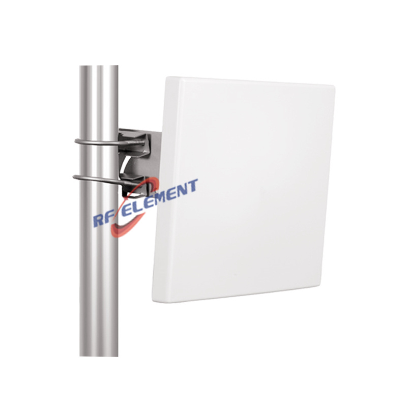
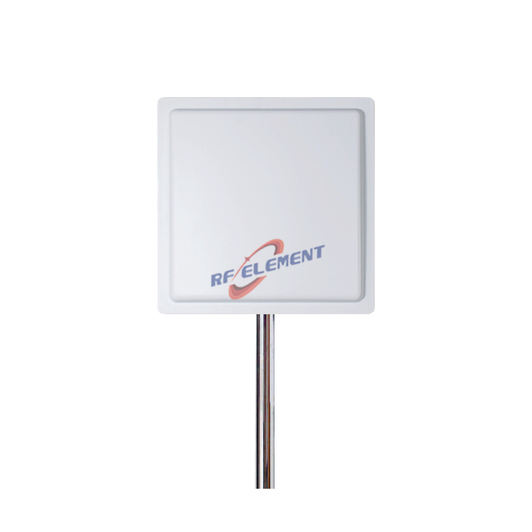
Gateway at the edge, sensors in one direction — a corridor, a valley, a field boundary. A directional panel buys range that no omni can match at the same height. An 11 dBi IoT panel antenna covering 900 to 930 MHz with a 55 degree beam puts the radiated energy where the nodes actually are, and its flat form keeps the wind load low on the mast.
The pattern to avoid is buying gain blind. Every extra dBi of omni gain narrows the vertical beam, and a 12 dBi collinear on a short rooftop will happily talk over the head of a sensor sitting 300 metres away at ground level. Match the beam to the geometry of the deployment, not to the biggest number on the product page. For the fuller taxonomy of antenna families and bands, the earlier guide to LoRa antenna types and applications covers the forms — omni, panel, Yagi, ceiling — and where each fits.
Keep the antenna clear of metal
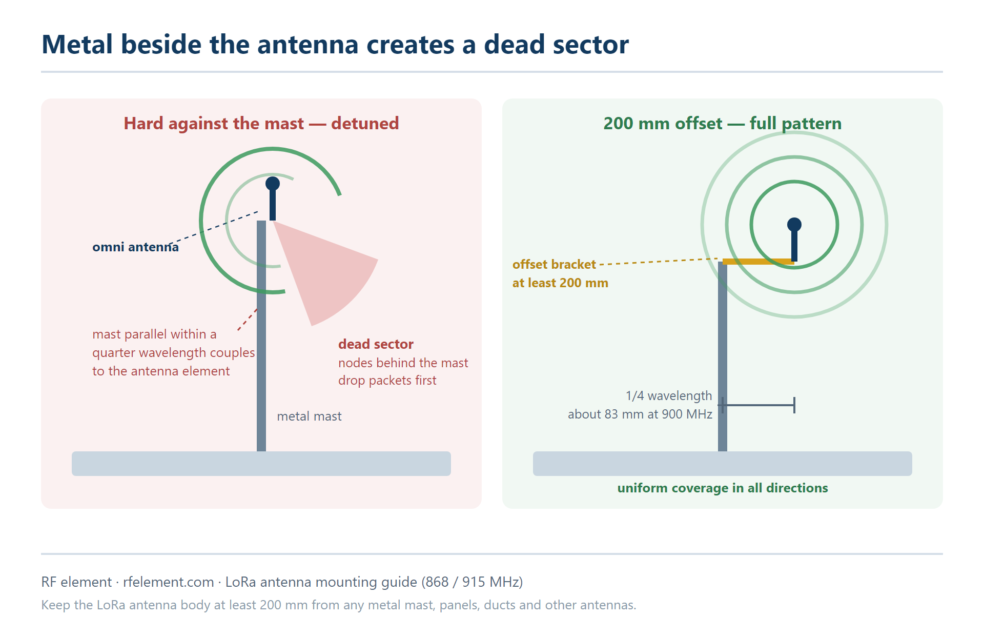
Metal near the antenna is the most common self-inflicted range problem in LoRa deployments, and the mast is usually the culprit. A vertical omni antenna mounted hard against a metal pole couples to it: the pole becomes part of the antenna, detunes it, and blocks part of the radiation pattern. The result shows up in the network as a dead sector — nodes on one side of the gateway report fine while nodes on the other side struggle, even at similar distances.
The geometry is simple. At 900 MHz a quarter wavelength is roughly 83 mm, so any mast running parallel to the antenna within that distance is inside the reactive near field. Our standing recommendation on the product pages is to keep at least 200 mm of clearance between the antenna body and any metal mast, using an offset bracket if needed. The same rule applies to everything else on the tower: keep the antenna above rooftop air-conditioning units, away from solar panels, and clear of cable trays. Other antennas on the same mast should sit at least a quarter wavelength to the side and preferably higher or lower rather than beside, and never in line with the LoRa antenna's boresight.
Treat the cable run as part of the antenna system
Gain lost in the feeder cable is gain that never reaches the air. Thin coaxial cable is expensive at sub-GHz in longer runs: RG-58, a common default, costs roughly a third of a decibel per metre at 900 MHz, so a ten metre run gives away around 3.5 dB — more than the difference between a 5 dBi and an 8 dBi antenna. Two mounting decisions control this without touching the antenna itself: mount the gateway indoors as close as practical to the antenna entry point, or keep long runs in thicker low-loss cable and check the arithmetic before specifying gain.
When the numbers start to matter — long runs, marginal sensors, a link you cannot afford to lose — put them into the link budget calculator rather than estimating. It takes transmit power, antenna gains, cable and connector losses and receiver sensitivity, and returns received power, margin and the maximum range the link can support. If the path grazes terrain or rooftops, the Fresnel zone calculator shows how much first-zone clearance the path needs at 868 or 915 MHz.
868 MHz or 915 MHz: buy for the region the network lives in
LoRa hardware is regional and the antenna must match the band, not just the technology. European deployments live in the 868 MHz band, North America in the 902 to 928 MHz ISM band, and parts of Asia follow AS923 regional plans. An antenna cut for 868 MHz still resonates near 915, but off-resonance operation costs efficiency where it hurts most — at the antenna's stated gain and match — so a network built for the United States should be specified with 915 MHz antennas and not "close enough" EU stock.
In practice the cleanest specification is a full-band LoRa antenna covering roughly 860 to 930 MHz. It removes the regional mismatch from the purchase decision entirely, which matters for fleets and OEM builds whose final market is not fixed at design time. Both LoRa omni antennas in our catalogue cover the 860 to 930 MHz span with either N-type or SMA termination.
A mounting checklist to run before ordering
Most LoRa range problems trace back to a handful of decisions made at installation time. Before ordering an antenna, run this list against the site:
Height: can the antenna go above the tallest local clutter? If not, what is the tallest obstacle it must clear, and at what distance?
Role: is this gateway surrounded by sensors (omni) or serving one direction (panel)?
Gain: are the sensors near and below (wider vertical beam, 5 dBi class) or far and at the horizon (tighter beam, 8 dBi class)?
Metal: is there at least 200 mm of clearance from the mast, and is the antenna clear of panels, ducts and other antennas?
Cable: how long is the run, what is the cable type, and what does that cost in dB?
Band: which region is the network in, and does the antenna cover it across the full 860 to 930 MHz span?
Send us the region, the planned gateway height and the spread of the sensor field, and we will indicate whether a 5 dBi or 8 dBi omni — or a directional panel — is the better match for the geometry. Samples of standard models ship in 3 to 5 working days, and connector type, cable length and mounting hardware can be specified with the order.
TAG:Where and How to Mount a LoRa Antenna for Maximum Range https://www.rfelement.com