5G n78 Omni Antenna | 3.5 GHz Fiberglass Omni Antenna
Achieve superior wireless connectivity with RF element's 3.5GHz Omni Antenna. Designed for 5G n78 (3500 MHz) band applications, this 11dBi gain antenna offers wide coverage and is perfect for DAS systems. Quick installation and reliable performance make it ideal for point to multiple point communications. Request a quote now!
Specifications
A 3400-3800 MHz omni antenna with 11 dBi gain is usually specified for n78 small cells and for point to multipoint links where subscribers sit all around the mast, yet the number that decides whether the site works is not the gain. It is the 8 degree vertical beamwidth. Eleven dBi from a 360 degree pattern can only be produced by squeezing the vertical plane, and an 8 degree slice covers a band of ground only a few tens of metres deep at the near edge, so the mounting height and the downtilt have to be chosen together with the antenna rather than after it. This page works through the geometry, the aperture, the matching across the 400 MHz of n78, and the mechanical details that matter on a pole.
What 8 degrees of vertical beamwidth actually covers
The half power beam is 8 degrees wide in elevation. Mounted with the pattern centre at 4 degrees below the horizon, the upper edge points at the horizon and the lower edge points 8 degrees down. The depression angle to a ground point at horizontal distance d from a mast of height h is the arctangent of h over d, so the lower edge lands at d equal to h divided by the tangent of 8 degrees, which is 7.1 times the mounting height. Everything closer than that sits below the beam and is served by the sidelobes only.
The arithmetic is worth doing before the pole is ordered. At 20 metres the near edge of the main beam is 142 metres out. At 30 metres it is 214 metres. If the subscribers you are trying to reach are closer than 7 times the height, an 11 dBi omni is the wrong pattern no matter how good the datasheet looks, and a 3 to 5 dBi omni with a 60 degree vertical beam will serve them better even though it carries 6 to 8 dB less gain. The two specifications have to be read together: a narrow vertical beam buys reach and gives up the near field.
Why the gain comes from the 630 mm length, not from the diameter
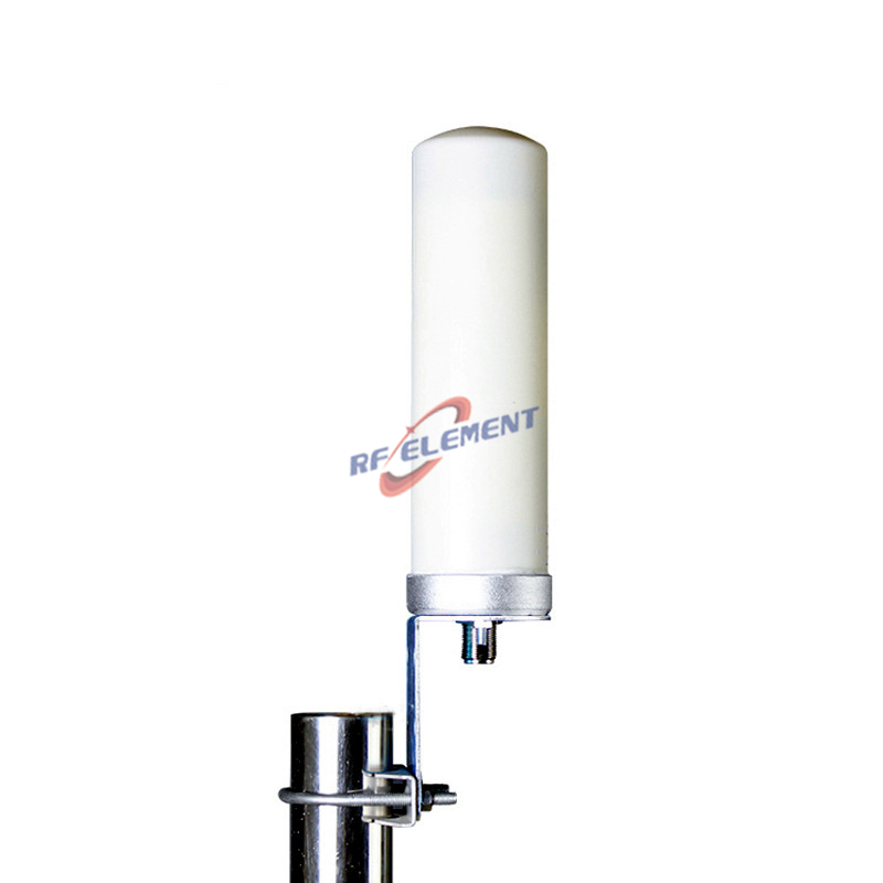
At 3.6 GHz the free space wavelength is 83 mm, so the 630 mm radome is 7.6 wavelengths long and its 42 mm diameter is half a wavelength. Those two ratios govern different things. The length in wavelengths sets the vertical beamwidth and therefore the gain. The diameter sets the bandwidth of the radiating structure and the wind load, and it does almost nothing for gain. This is why a thicker rod of the same length does not add dBi, and why a supplier who quotes more gain from a shorter radome is either using a narrower beam or a different number.
The gain over a half wave dipole is 8.9 dB, from 2.15 dBi for the dipole to 11 dBi for this antenna. A uniformly fed collinear array adds 10 log of N decibels for N elements, so 8.9 dB corresponds to roughly eight radiating sections. The remaining length carries the feed line, the matching section and the taper at each end that holds the sidelobes down. None of that is visible from outside, which is why the radome length is the only external clue a buyer gets.
Reading 11 dBi against the 41253 rule
The 41253 rule estimates directivity from the two half power beamwidths: divide 41253 by the product of the horizontal and vertical angles in degrees. For this antenna that is 41253 divided by 360 times 8, which gives 14.3 in linear terms, or 11.6 dBi. The datasheet says 11 dBi. The half decibel difference is the aperture efficiency, about 88 percent, which is a normal figure for a collinear array with a radome over it.
The value of the check is that it works on any datasheet, including a competitor you have never bought from. If a page claims 14 dBi from a 360 by 8 degree pattern, either the vertical beam is narrower than stated or the gain is optimistic by 2.4 dB. Both are worth a question before the purchase order, and the question is cheap to ask because the two numbers are already on the page.
| Frequency Range | 3400-3800MHz | |
| Polarization | Vertical | |
| Gain(dBi) | 11 | |
| Horizontal Beamwidth | 360° | |
| Vertical Beamwidth | 8° | |
| Impedance | 50Ω | |
| VSWR | ≤ 1.8 | |
| Maximum Power | 50W | |
| Connector Type | 1 Port, N-Type Female/ N-Type Male | |
| Antenna Dimension(mm) | Φ 42*630 | |
| Net Weight | 1.0 kg | |
| Operating Temperature | -55° to +60° C (-67° to +140° F) | |
| Radome Material | Fiberglass | |
| Radome Color | White/Grey | |
| Mounting Options | Pole Mounting | |
VSWR 1.8 across 400 MHz of n78
Band n78 runs from 3300 to 3800 MHz, which is 500 MHz wide. This antenna covers 3400 to 3800 MHz, which is 400 MHz. The lower 100 MHz is outside the specified range, and that is the first thing to confirm against the operator plan: a network using 3300 to 3400 MHz needs a different product, not a promise that it will probably work. Where the plan sits inside 3400 to 3800 MHz, the full band is covered with a single N-Type port and no tuning.
A VSWR of 1.8 corresponds to a reflection coefficient of 0.286, a return loss of 10.9 dB and a mismatch loss of 0.37 dB. That is the worst case at the band edges. In the middle of the band the match is normally better, and the loss falls below 0.2 dB. For a link budget the 0.37 dB figure is what should be entered, not the typical value, because the edges are where the channel may actually be assigned.
Mounting height, downtilt and the far edge of the cell
Because the beam is only 8 degrees deep, the downtilt setting has more effect than on a 65 degree omni. One degree of tilt moves the lower edge from 7.1 times the height to 5.7 times the height, a change of 20 percent in where coverage starts. A mast that is re-used from an earlier installation therefore needs the tilt recalculated rather than copied, and the mechanical tilt bracket should have a scale fine enough to resolve one degree.
The mechanical load is modest. The radome presents 0.027 square metres of frontal area, which at 40 metres per second wind is about 31 newtons, and the whole antenna weighs 1.0 kg. A standard pole clamp is enough. What deserves attention instead is the connector: a single N-Type female or male port at the bottom of a 630 mm rod is a long lever arm, and a stiff jumper will work the joint loose over a season. A short flexible tail with a drip loop costs little and removes the problem. For subscriber premises where the radio and the antenna share one housing, the 5G omni antenna covers 698 to 4200 MHz with a much wider vertical beam and is the better fit there; the rest of the range sits on the 5G antenna page. For installations that need to compare this pattern against sector or panel options, the antenna selector filters the catalogue by frequency, gain and pattern shape.
Send your requirement to sales@rfelement.com with the band, the mounting height and the coverage radius, and we will confirm whether this pattern fits or whether a wider vertical beam is the better choice.
FAQ — 5G n78 Omni Antenna
What is the 5G n78 Omni Antenna used for?
What frequency band does the 5G n78 Omni Antenna cover?
What are the key specifications of the 5G n78 Omni Antenna?
Can RF element customize the 5G n78 Omni Antenna for my application?
What is the MOQ and lead time for the 5G n78 Omni Antenna?
How do I get a quotation for the 5G n78 Omni Antenna?