65 vs 90 Degree Sector Beamwidth: Which to Specify
At the same band and vertical beamwidth, a 65 degree sector concentrates power into a narrower arc, adding roughly 1.5 dB and keeping more of it out of the neighbouring sector. A 90 degree sector covers 25 degrees more arc with fewer sites but lower gain per direction. The sector plan decides, not the datasheet.
Both options are standard catalogue items, and both will light up a site. The difference shows up at the cell edge: one gives you a cleaner signal-to-interference ratio, the other gives you coverage where a third sector would otherwise be needed. This guide sets out the numbers behind that trade, so the specification holds up when the RF plan is reviewed.
What the 65 and 90 degree figures actually measure
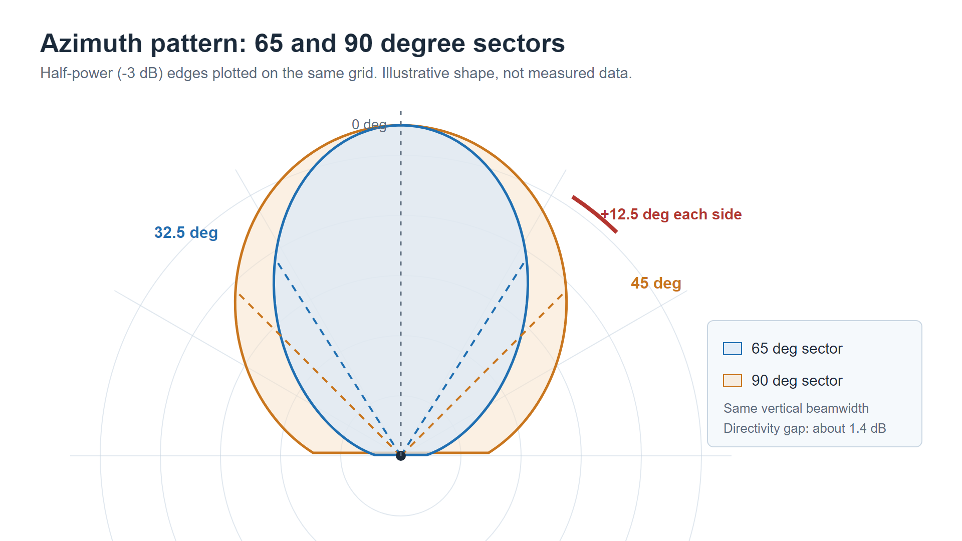
Both numbers are the azimuth half-power beamwidth, usually written HPBW. It is the angular width over which radiated power stays within 3 dB of the peak. A 65 degree sector antenna therefore reaches 32.5 degrees either side of boresight before the pattern crosses the -3 dB line; a 90 degree sector reaches 45 degrees either side.
Two details matter when reading a datasheet. First, the pattern does not stop at -3 dB. It keeps rolling off through -10 dB and -20 dB, and where that roll-off lands decides how much energy arrives in the next sector. Second, the nominal figure carries a production tolerance: our 90 degree 4G sector is specified at 90 plus or minus 5 degrees, and the 65 degree class is typically held to the same window.
The vertical beamwidth is a separate number and is often overlooked. A 65 degree panel may be 7 degrees tall in the vertical plane while a 90 degree panel of similar length sits at 9 to 18 degrees. That difference changes where the energy lands on the ground, which is covered further down.
The gain gap is about 1.5 dB at the same band, not 3
Sector antennas are frequently sold on the claim that 65 degrees buys 3 dB over 90 degrees. That figure only holds if the vertical beamwidth narrows at the same time. When the vertical pattern is unchanged, the real difference is closer to 1.5 dB.
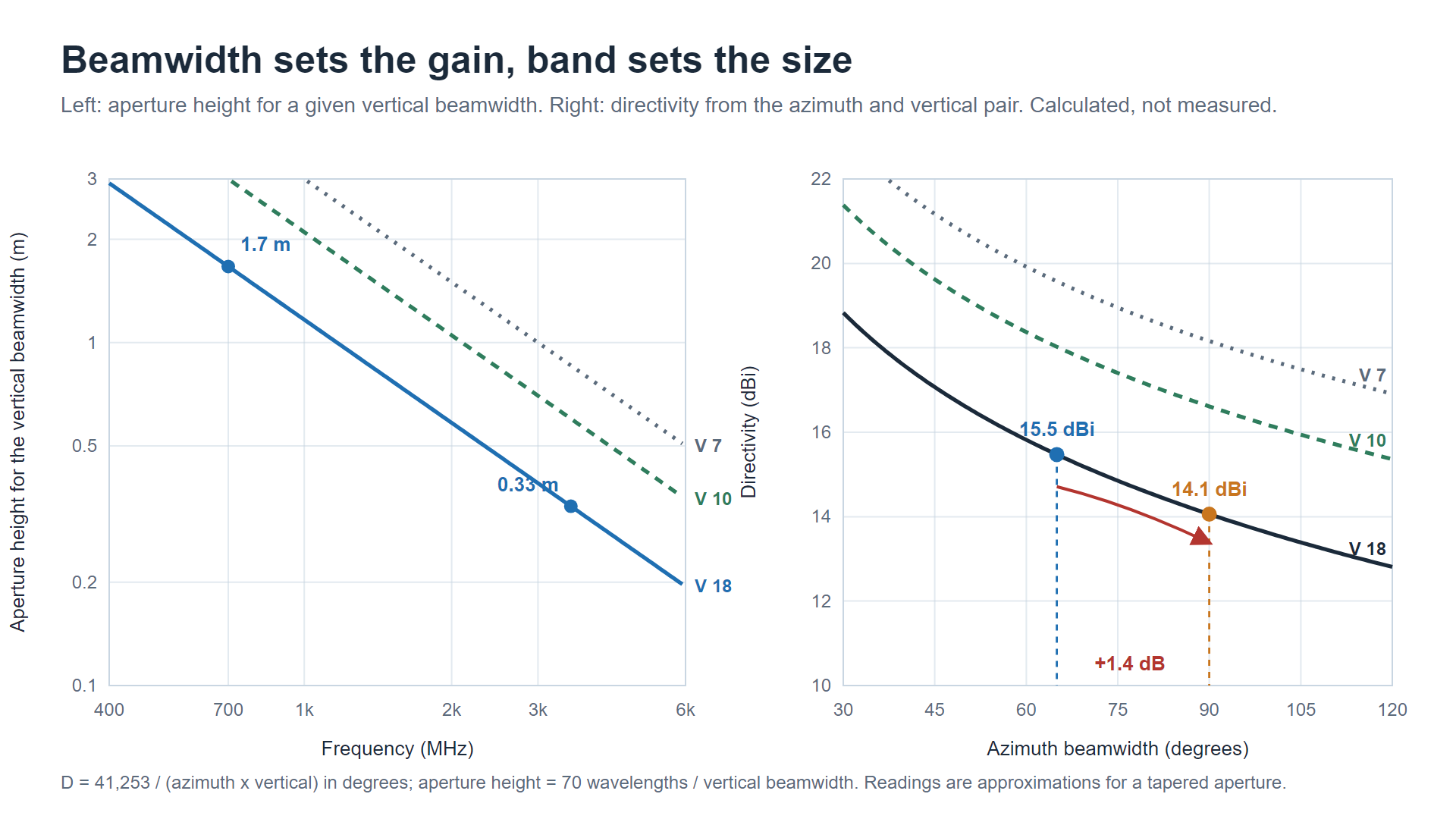
The estimate comes from the directivity of a rectangular aperture. For a beam with horizontal beamwidth H and vertical beamwidth V, both in degrees, directivity in dBi is approximately:
D = 10 x log10 ( 41,253 / (H x V) )
The constant 41,253 is the full sphere expressed in square degrees. Running the common combinations gives the table below. Real gain sits 0.5 to 1.5 dB under these figures because of aperture efficiency, but the difference between columns is what matters here.
| Azimuth x vertical beamwidth | Directivity | Gap to 90 degrees |
|---|---|---|
| 65 x 7 degrees | 19.6 dBi | 1.4 dB |
| 90 x 7 degrees | 18.2 dBi | reference |
| 65 x 10 degrees | 18.0 dBi | 1.4 dB |
| 90 x 10 degrees | 16.6 dBi | reference |
| 65 x 18 degrees | 15.5 dBi | 1.4 dB |
| 90 x 18 degrees | 14.1 dBi | reference |
So the horizontal narrowing is worth about 1.4 dB of directivity on its own. Where the extra decibel comes from is the vertical plane: a 65 degree sector designed for high gain usually also compresses vertically, and that is what pushes the published figure towards 2 dB or more. If a supplier quotes 3 dB with an unchanged vertical beamwidth, ask for both patterns.
Our 90 degree 4G LTE sector antenna is specified at 12 dBi across 698 to 960 MHz and 15 dBi across 1710 to 2700 MHz, with vertical beamwidth of 18 and 9 degrees respectively. A 65 degree panel of the same physical length would land roughly 1.5 dB higher on the same band, and the difference in coverage shape would be larger than the difference in gain.
Gain, beamwidth and band are one equation
Gain quoted without a beamwidth is a marketing number, and a beamwidth quoted without a band is only half a specification. The three parameters are tied together by two relations, and neither works without the other.
Directivity comes from the angles alone:
D = 10 x log10 ( 41,253 / (H x V) )
Physical size comes from the angles and the band together. A rough rule for a tapered aperture is 70 wavelengths divided by the beamwidth in degrees, for both planes:
Aperture height = 70 x wavelength / V, aperture width = 70 x wavelength / H
Running both relations across the bands a sector site actually uses gives the table below. Sizes are the radome dimensions a 65 or 90 degree pattern needs before efficiency losses, and the directivity column never changes, because the angles never change.
| Band | Wavelength | 90 x 18 degrees: width x height | 65 x 18 degrees: width x height | Directivity, 90 / 65 |
|---|---|---|---|---|
| 700 MHz | 43 cm | 0.33 x 1.67 m | 0.46 x 1.67 m | 14.1 / 15.5 dBi |
| 900 MHz | 33 cm | 0.26 x 1.30 m | 0.36 x 1.30 m | 14.1 / 15.5 dBi |
| 1800 MHz | 17 cm | 0.13 x 0.65 m | 0.18 x 0.65 m | 14.1 / 15.5 dBi |
| 2600 MHz | 12 cm | 0.09 x 0.45 m | 0.12 x 0.45 m | 14.1 / 15.5 dBi |
| 3500 MHz | 8.6 cm | 0.07 x 0.33 m | 0.09 x 0.33 m | 14.1 / 15.5 dBi |
Read the last column twice. The gain difference between 65 and 90 degrees is 1.4 dB at 700 MHz, at 1800 MHz and at 3.5 GHz alike, because gain follows the angles. What the band buys or costs is the size column: the same 65 degree, 18 degree vertical pattern is a 0.46 m wide, 1.67 m tall radome at 700 MHz and a 0.09 m wide, 0.33 m tall panel at 3.5 GHz, and the wind load scales with it. This is why low-band sector antennas are usually catalogued at 90 degrees and 12 dBi in a compact radome, and why a 65 degree low-band unit is a metre or more tall. If a supplier lists 65 degrees at 700 MHz in the same housing as the 90 degree version, ask for the measured azimuth pattern.
The converse explains why a datasheet gain number is meaningless without its band. For a fixed aperture, doubling the frequency adds about 6 dB, so a 12 dBi label at 900 MHz and a 12 dBi label at 3.5 GHz describe very different hardware: the low-band version needs roughly four times the linear aperture to hold the same pattern. When a catalogue quotes gain, check that the band travels with it, and compare 65 against 90 degree candidates inside one band and one vertical pair, or the comparison stops carrying information.
The site plan decides, not the datasheet
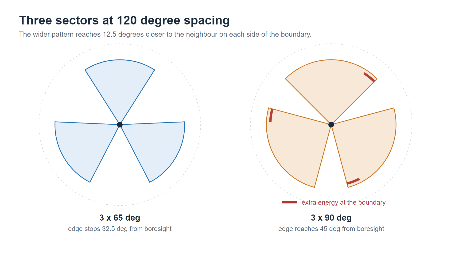
A three-sector site places boresights 120 degrees apart. With 65 degree panels, the -3 dB edge of each sector stops 32.5 degrees from its boresight, well inside the 60 degrees to the sector boundary. With 90 degree panels, the edge reaches 45 degrees, which is 12.5 degrees closer to the neighbour. That extra arc is not free: the field strength arriving at the neighbour cell edge rises, and the two sectors compete for the same users along the boundary.
Where the site is capacity-limited, that competition is the whole problem. A narrower sector keeps its own users on its own carrier, and the antenna contributes to SINR before any baseband feature is applied. Where the site is coverage-limited and the operator wants to avoid building a fourth site, the wider sector earns its place.
The practical rule is short. Dense grid with tight reuse: specify 65 degrees. Wide rural arc where site count is capped: specify 90 degrees. Mixed plans are common, and they are covered below.
Interference and SINR: what the extra 25 degrees costs
In a three-sector site, co-channel interference between sectors is set by how much energy each antenna sends sideways. A 65 degree panel puts its -3 dB edge 12.5 degrees further from the neighbour than a 90 degree panel does, and its pattern is already 3 dB down at that point. Across a cluster of sites, the effect compounds: every site in the ring is doing the same thing.
That matters because higher-order modulation needs margin. The step from 64QAM to 256QAM is bought with several dB of SINR, and an antenna that removes 1.5 to 2 dB of interference is contributing to that budget for free, without adding power or changing the radio plan. Front-to-back ratio belongs in the same conversation: both our 90 degree sector and the 65 degree class are specified above 20 dB, which keeps the pattern from wrapping around the mast.
Where 90 degrees wins outright
There are real sites where the narrower sector is the wrong answer.
A rural macro site covering a valley, a coastal strip or a highway corridor often has no second site to fall back on. Widening from 65 to 90 degrees adds 25 degrees of arc, and that arc may be the difference between covering a village and not covering it. The same logic applies to two-sector sites built to keep site count down, and to pole-mounted small cells where the antenna has to serve a street in both directions from one position.
Indoor and venue work is another case. A wall-mounted panel feeding a hall, a platform or a warehouse aisle is usually chosen for the arc it covers rather than for peak gain, because the link distances are short and the ceiling height limits how much downtilt can be applied.
Vertical beamwidth and downtilt belong to the same decision
Horizontal beamwidth gets the attention, but the vertical pattern decides whether the site has a hole underneath the mast. A narrow vertical beam with heavy downtilt puts the first null close in, and users standing under the antenna pay for it. Wider vertical beamwidth fills that region but throws energy at the horizon, where it becomes interference for the next site.
This is why the 90 degree 698 to 960 MHz pattern uses 18 degrees of vertical beamwidth while the same antenna narrows to 9 degrees at 1710 to 2700 MHz. The low band needs the broader vertical pattern to hold coverage; the high band can afford a tighter one because the link budget is better. When comparing a 65 and a 90 degree candidate, compare the vertical pair as well. A 65 degree antenna with 7 degrees vertical is a different tool from a 90 degree antenna with 18 degrees vertical, even though both are sold as sector antennas.
Specification checklist
Before the purchase order goes out, confirm these points against the RF plan:
Sector count and boresight spacing, so the azimuth beamwidth matches the reuse pattern.
Required gain at the cell edge, not peak gain at boresight.
The band attached to every gain figure, since the same aperture returns more gain at a higher frequency and a bare dBi number cannot be compared across bands.
Vertical beamwidth against site height and planned downtilt, including null fill where the site is tall.
Front-to-back ratio above 20 dB, and sidelobe suppression if the site shares spectrum with a neighbour.
Port count and polarisation, since a 2x2 cross-polarised sector behaves differently from a single-polarised one at the edge.
Wind load and radome size, which grow with the aperture and matter on exposed masts.
If the site is 5G N78, the same reasoning applies with a shorter wavelength, but the numbers are not interchangeable across bands. Our 5G n78 MIMO panel antenna runs 65 degrees horizontal with 28 degrees vertical across 3300 to 3800 MHz, which works out at about 13.6 dBi of directivity before aperture efficiency and lands at 12 dBi on the datasheet. That is lower than the 90 degree low-band sector above, because the vertical pair is much wider, not because the azimuth is narrower. The shape suits dense small-cell grids rather than wide rural coverage. Compare 65 and 90 degree candidates inside one band and one vertical pair, or the comparison stops carrying information.
Frequently asked questions
How much gain do I gain going from 90 to 65 degrees?
About 1.5 dB if the band and the vertical beamwidth stay the same, which is what the directivity calculation predicts. Published differences of 2 to 3 dB usually come from a narrower vertical pattern as well, not from the azimuth change alone.
Can I mix 65 and 90 degree sectors on one site?
Yes, and it is common on sites where one face needs to reach further than the others. Keep the boresight spacing consistent with the wider antenna and record the tilt of each sector separately, otherwise the overlap at the boundary will not match the plan.
What about vertical beamwidth and downtilt?
Treat them as part of the same choice. A narrow vertical beam with heavy downtilt creates a coverage hole near the mast; a wide vertical beam fills it but sends more energy towards the horizon. Check the vertical pattern at the planned tilt before ordering, not only the horizontal figure.
If you are weighing 65 and 90 degree sectors for a 4G or 5G rollout, send the sector plan and band plan to our engineering team. We will come back with the pattern that fits the site, and the datasheet to prove it.
TAG:65 vs 90 Degree Sector Beamwidth: Which to Specify https://www.rfelement.com