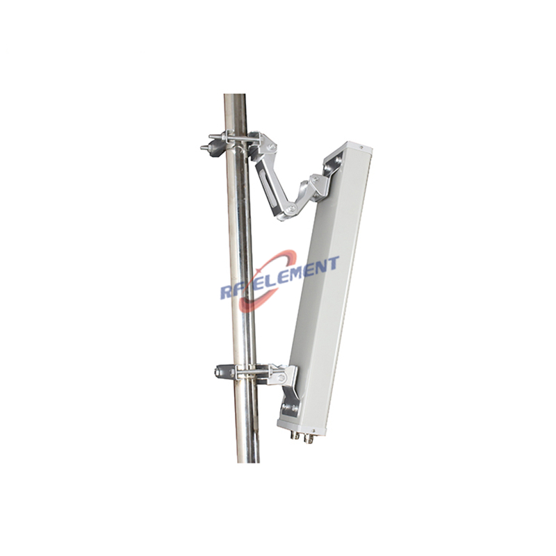
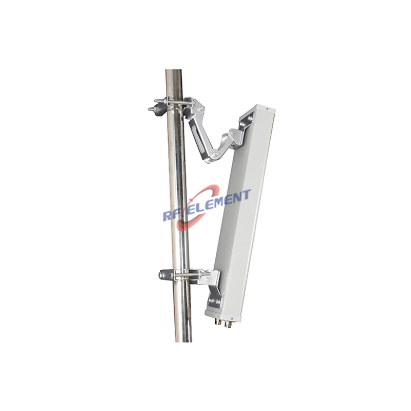
4G LTE Sector Antenna | 90-Degree Outdoor Sector Antenna
Request a quote now to experience seamless connectivity with our 4G LTE sector antenna.
Specifications
A 90 degree sector for 698-2700 MHz, 900 mm tall, with 12 dBi at the low band and 15 dBi at the high band from a single vertical polarization. The vertical beam is 18 degrees below 960 MHz and 9 degrees above 1710 MHz, VSWR is at or below 1.5, the front to back ratio is above 20 dB, and two N-Type female ports are provided on a 100 W rating. The PVC radome is grey and the unit weighs 5.5 kg.
Ninety degrees and four sectors
Four sectors of 90 degrees tile a full 360 degrees with no overlap at the half power points, which makes this the panel for a four sector site where every direction has to be served. A three sector site would use 65 degree panels and accept 15 degrees of overlap instead. The choice is usually capacity: four narrower sectors carry more traffic per square kilometre, at the cost of a fourth radio chain.
At the sector edge, 45 degrees off boresight, a 90 degree panel is 3 dB down. Users on the boundary therefore sit on the cell edge by design, and their throughput is set by the interference from the neighbouring sector rather than by the antenna. If the site has to hold a hard cell edge, the four sector plan with 90 degree panels is the easier one to model.
Fifteen decibels from a 900 mm aperture
The gain comes from vertical aperture, and so does the narrow beam. A 900 mm array is about two wavelengths at 700 MHz and seven at 2.6 GHz, which is why the vertical beam goes from 18 degrees to 9 degrees and the gain from 12 dBi to 15 dBi. The horizontal beam stays at 90 degrees plus or minus 5 in both bands.
A 9 degree beam is sensitive to tilt. One degree of mechanical error moves the pattern by about a ninth of its beamwidth, which on a 1 km link shifts the peak by roughly 17 m of ground distance. Set the tilt with an inclinometer rather than by eye, and re-check it after the clamp is fully torqued.
| Frequency Range | 698-2700MHz | |
| Frequency Sub-Range | 698-960 MHz | 1710-2700 MHz |
| Polarization | Vertical | |
| Gain(dBi) | 12 | 15 |
| Horizontal Beamwidth | 90±5° | |
| Vertical Beamwidth | 18° | 9° |
| Impedance | 50Ω | |
| VSWR | ≤ 1.5 | |
| Front to Back Ratio(dB) | >20 | |
| Maximum Power | 100W | |
| Connector Type | 2 Port, N-Type Female | |
| Antenna Dimension(mm) | 900*325*140 | |
| Net Weight | 5.5 kg | |
| Operating Temperature | -55° to +60° C (-67° to +140° F) | |
| Radome Material | PVC | |
| Radome Color | Grey | |
| Mounting Options | Pole mounting | |
Single vertical polarization, two ports
Both ports sit on the same vertical polarization. That is not a cross polarized pair, so the antenna does not provide polarization diversity and will not support 2x2 MIMO by polarization. What it does provide is the highest gain in the 4G sector group, because all of the aperture is spent on one pattern instead of being split between two slants.
This is the right panel where the radio has a single transmit chain, where the link is a donor or backhaul path with a fixed remote, or where the two ports feed a transmit and receive split rather than a MIMO pair. Where the radio expects a cross polarized pair, the slant 45 sector is the correct part and this one is not.
5.5 kg and 0.29 square metres
The frontal area is 0.9 m by 0.325 m, about 0.29 square metres, and the mass is 5.5 kg. At 40 m per second the drag is near 280 N, which a 50 mm mast and a two bolt clamp will carry, but the clamp has to be at the centre of pressure rather than at the base of the housing. Mount at mid height of the panel and add a second clamp if the pole is above 3 m.
The 140 mm depth gives the front to back ratio of more than 20 dB. Keep that rear face clear: a standoff bracket that crosses the back of the housing will fill the back lobe, and on a shared mast the sector behind will see the difference immediately.
Where this panel earns its size
The usual application is a rooftop or a small macro site that has to cover a long, narrow area such as a highway, a rail corridor or a port quay. 15 dBi at 2.6 GHz with a 9 degree vertical beam throws the energy along the ground rather than into the sky, which is the whole reason to accept a 900 mm housing.
For a DAS donor link the same panel works if the donor is a single polarized signal, and the front to back ratio keeps a second cell off the back. For an in building DAS the size is the obstacle: 900 mm does not fit a ceiling void, so the ceiling antenna family is the correct place to look.
Ordering
Two N-Type female ports on a single vertical polarization, grey PVC radome, pole clamps. Samples in 3-5 days, production in 15-25 days.
Where the radio needs a cross polarized pair for 2x2 MIMO, the 4G LTE MIMO sector antenna with a slant pair trades 6 dB of gain for polarization diversity. Where several high power carriers share the mast and PIM is the constraint, the 4G LTE low PIM omni antenna is rated at 150 dBc.
Send the sector count, the tilt, the radio chain count and the mast diameter. The sector count fixes the beamwidth, the chain count decides whether a cross polarized pair is needed, and the mast diameter decides the clamp.
FAQ — 4G LTE Sector Antenna
What is the 4G LTE Sector Antenna used for?
What frequency band does the 4G LTE Sector Antenna cover?
What are the key specifications of the 4G LTE Sector Antenna?
Can RF element customize the 4G LTE Sector Antenna for my application?
What is the MOQ and lead time for the 4G LTE Sector Antenna?
How do I get a quotation for the 4G LTE Sector Antenna?