

How We Designed Our 3200-3800MHz 5G Antenna
Datasheets make antennas look simple. One gain number, one VSWR curve, a few mechanical drawings, done. After years of designing radiators for base station and fixed wireless access systems, we can tell you the useful information usually sits between the lines. So in this article we take one of our own products, a 3200-3800MHz dual-polarized directional radiator, and explain its measured gain and VSWR the way we would explain them to a customer across the table.
A quick word on the band
The 3200-3800MHz range covers n78 and the upper part of n77, where most 5G NR networks in Europe, the Middle East, and Asia are actually built. At 3.5GHz the free-space wavelength is about 86mm, which makes directional behavior achievable with a compact element instead of a large reflector. The flip side is propagation: signal loss through walls and trees at these frequencies is far worse than below 1GHz, so link budgets lean heavily on antenna gain. And because the element is dual-polarized, two orthogonally fed ports give the radio two decorrelated signal paths. In a multipath environment the two channels fade independently, and MIMO processing turns that into more stable throughput at the cell edge.
Gain: 9.1 to 9.6 dB, and what it means
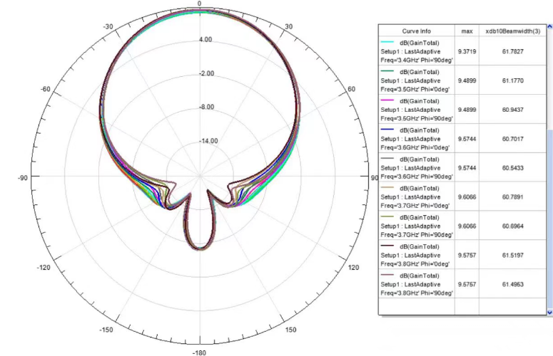
Measured peak gain on this unit is 9.1168 dB at 3.2GHz and 9.5757 dB at 3.8GHz.
The rise with frequency is expected, not luck. Directivity scales roughly with the square of the radiator's electrical size, and electrical size is physical size divided by wavelength. From 3.2 to 3.8GHz the same geometry grows about 19% in wavelengths, so the beam tightens and gain follows. A smooth upward trend like this is what a healthy design looks like. Ripples or sudden dips in that trend would be a warning sign of pattern breakup.
In practical terms, 9.5 dB over isotropic means roughly nine times more radiated power in the boresight direction. On a marginal FWA link that is frequently the difference between a usable modulation scheme and a dropped connection. It also tells you the beamwidth: a planar element around this gain typically shows half-power beamwidths near 60-70 degrees, which is exactly why elements like this one get built into sector panels, where four to eight of them together reach 15-18 dB.
One thing buyers should always ask: what is the gain flatness? Peak gain is measured at the best point in the band, but the radio transmits across the entire 600MHz. The 0.46 dB spread measured here is tight, meaning no channel is disadvantaged. And gain is not the only consideration in pattern design. Higher boresight gain achieved at the cost of larger sidelobes degrades interference performance, so the real engineering trade is gain against sidelobe and backlobe control.
VSWR: the quiet number that decides reliability
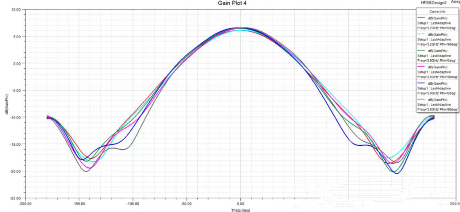
VSWR describes how well the antenna's input impedance matches the 50-ohm feed line, and it deserves more attention than it usually gets. The arithmetic is unforgiving. A VSWR of 1.5 is a return loss of about 14 dB, roughly 4% of the transmitter's power reflected. At VSWR 2.0 that rises to about 11%. On a 40W carrier, the difference is several watts of heat continuously dumped onto the radio's output stage, often inside a cabinet sitting at 60 degrees Celsius in the sun. Reflected power is also what trips VSWR foldback protection on modern radios, which reduces output power exactly when the network is busiest.
Across 3-4GHz, the terminal VSWR curve on this radiator stays low and flat, with no spike near the band edges. That flatness is the part cheap designs fail. Their match is tuned at mid-band and drifts out of spec toward 3.2 or 3.8GHz, precisely where operators are now deploying. A flat curve tells you the match structure has real bandwidth margin, and it also means the element survives imperfect field conditions, a marginal connector, a slightly damaged feeder, without the match collapsing.
For a dual-polarized unit, add a third metric: port-to-port isolation. The two polarization ports need to be decoupled by 25 dB or better, or the MIMO channels bleed into each other and the whole point of dual polarization quietly disappears. We measure it on every design iteration alongside VSWR.
Gain and VSWR trade against each other

These two specs are not independent. Widening the match bandwidth usually costs directivity, and pushing gain up usually narrows the match. The design target on this element was to hold peak gain above 9.1 dB across the band while keeping VSWR low and flat from 3 to 4GHz. That constraint set, not the biggest number on the datasheet, is what consumed the tuning iterations. It is also how we suggest judging any 5g antenna manufacturer: look at whether the curves hold at the band edges and at port two, not at the headline figure in the middle of the band.
Three questions before you order
What are gain and VSWR at 3.3 and 3.7GHz specifically, not just mid-band?
What is the port isolation, and is it measured or simulated?
Can you share the raw measurement data, including patterns in both principal planes?
A supplier who answers without hesitation is a manufacturer. If you want the full measured dataset for this radiator, patterns and isolation included, contact our team. We ship evaluation samples, and we are used to buyers who check the numbers.
TAG:How We Designed Our 3200-3800MHz 5G Antenna https://www.rfelement.com
