RFID Antenna Manufacturer: RF element Custom Solutions for Global IoT Applications
UHF RFID lives in a narrow window of spectrum and in a wide range of buildings. Our fixed panels are specified for 900-930 MHz — the span that covers the 902-928 MHz ISM allocations used across the Americas and the adjacent windows deployed in other regions, all read by EPC Gen2 (ISO 18000-6C) class readers. Inside that one band we keep four fixed panels and one fiberglass omni in production, all vertically polarized, all with VSWR no higher than 1.5 and rated 50 W on the connector, and all built so the read zone — not the catalogue gain — is the thing you actually choose.
Why one band and five shapes, rather than a wider catalogue? Because an RFID deployment is decided by geometry. A reader is only as good as the field its antenna lays over the tags, and the tags in a warehouse sit on carton spines, forklift frames, totes on a conveyor and the occasional asset that left the building. The five parts below are the same electrical design stretched across five beam shapes, which is what lets a project move from a dock-door pilot to an aisle rollout without changing vendors, connectors or mounting practice.
The four panels, side by side
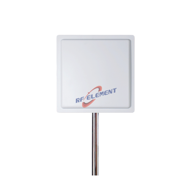
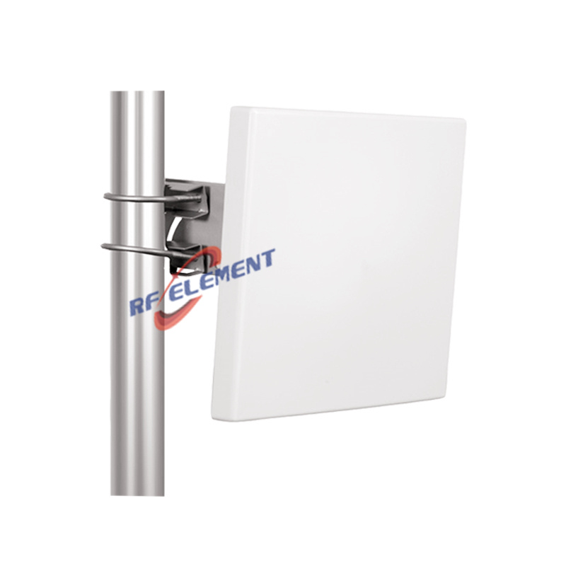
The 915MHz RFID panel antenna with 9 dBi gain is the doorway specialist: 65° horizontal by 60° vertical beam, a 260 × 260 × 45 mm, 1.3 kg body on a single N-type female port. Step up to the 11 dBi IoT panel antenna and the beam tightens to 55° by 50° while the plate grows to 370 × 370 × 20 mm at 2.5 kg. The 13 dBi high gain RFID panel narrows further to 38° by 41° on a 450 × 450 × 40 mm, 3.0 kg plate — the long, narrow read zone part. Where approach direction cannot be predicted, the 8 dBi fiberglass omni trades that directionality for a 360° horizontal pattern inside a 16° vertical beam on a Φ42 × 1540 mm tube at 1.5 kg, pole-mounted where a portal does not exist.
Every one of them is an ABS radome, rated -55° to +60° C, with mounting hardware matched to the weight class. None of the four asks for a licence, a controller or a firmware conversation — they are panels, and they behave like panels. That is the whole line, and the specification deltas between the four are the design tool.
Matching beamwidth to the read zone
A dock door portal is a short-standoff, wide-target problem: the 65° beam of the 9 dBi panel mounted at the jamb covers the opening without spilling into the lane beside it. An aisle or a conveyor spine is the opposite — a long, narrow corridor of reads — and the 38° beam of the 13 dBi panel lays that corridor down the aisle instead of into the racking. Between them, the 55° of the 11 dBi panel is the part we quote when one plate must cover a pallet position and part of the approach. Reading range grows with gain, but so does the geometry you must control; the panel with the most dBi is rarely the panel with the fewest stray reads.
The same logic extends to the awkward rooms. Cold stores and wet docks want the ABS radome and the temperature rating rather than anything exotic; yard and vehicle-gate applications want the fiberglass omni on a mast, because trucks present themselves from every bearing and a panel that must serve all of them ends up serving none of them well. When a sketch lands with both problems in one building, the answer is usually two part numbers, not one compromise.
Polarization and what the tags are doing
Our UHF panels are vertically polarized — one linear field per port. Portal geometries keep tag orientation predictable — labels on carton spines passing a fixed frame — and vertical polarization matches them cleanly. Where tags arrive in mixed orientation, the fix belongs on the reader side with its receive diversity, and the panel's job stays what it is: putting a defined field shape into a defined zone. We would rather say that plainly than sell a polarization the hardware does not have.
Power handling and the multi-reader floor
Every panel in the line is rated 50 W and terminates in one N-type connector, which is worth more in a dense deployment than it looks. Passive panels add no noise of their own; what raises a site's read floor is energy arriving where it was not aimed, and that is a beam-shape decision. Keep each panel's field inside its zone, stagger the reader channels, and the site scales reader by reader without the readers hearing each other's tags. When the project later grows, the panels stay put: same plate, same bracket, same cable practice, one more channel-plan entry. The 50 W rating, meanwhile, exists so that regional power limits and reader capabilities are never the antenna's problem — the connector and the plate are rated well past anything a Gen2 reader will ask of them.
Where the wrong choice shows up
The 13 dBi, 38° panel on a narrow doorway reads the far side of the wall, the forklift lane behind it, and the neighbouring reader's zone — stray reads and PLT collisions follow, and the blame usually lands on the software. The 8 dBi omni aimed at a long-range dock read does the reverse: it spends its 360° pattern on empty yard in every direction, drags the noise floor up for every reader on site, and still closes fewer reads than a panel of half the aesthetic appeal. And a Φ80 × 27 mm puck is the wrong tool where a 260 × 260 mm plate is wanted — the puck exists for assets, not for portals.
When the asset itself reports
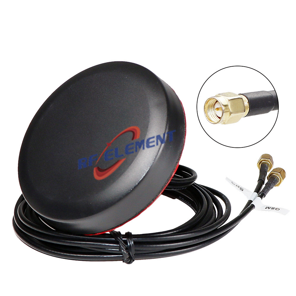
Tracking applications increasingly put the radio on the asset, and that is where our 4G/5G GPS puck antenna fits: a cellular sub-range of 700-3800 MHz with gain of at least 3 dBi, a second sub-range at 1575.42±5 MHz for GNSS listed at ≥28, two SMA male ports, a Φ80 × 27 mm, 0.2 kg housing in black ABS, and a -40° to +60° C rating for the harsher mounting points. Fasteners and screws for pole mounting ship with it, and at 0.2 kg the structural conversation ends before it starts. One puck carries the report and the position fix together, which is usually the whole bill of materials for a tracker's antenna side.
Built to order, not adapted
All of the above is manufactured in our own house, and OEM/ODM runs on the same line, not a different one: connectors, cable runs, brackets, radome colour and the mechanical envelope all move to order, and gain and beamwidth are retuned within the existing housing design when your read-zone sketch demands it. Evaluation samples ship inside a week once the drawing is signed off; volume scheduling follows agreed quantities, and MOQ leaves a single portal pilot free to run before any rollout commitment. Put the read-zone sketch, the reader's regional band, and the mounting drawing into a message for sales@rfelement.com — the answer comes back with the chosen panel, its specification sheet, and the mounting plan, so the configuration you quote with is the configuration the read zone actually delivers. RFID shares its 900 MHz neighbourhood with LoRa, and for mixed fleets our LoRa antenna line covers the same band from the same factory.
TAG:RFID Antenna Manufacturer: RF element Custom Solutions for Global IoT Applications https://www.rfelement.com