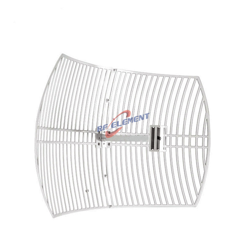
Dual Band WiFi Parabolic Grid Antenna | 2.4GHz/5GHz 15dBi
Specifications
A 300 by 400 mm dual band parabolic grid antenna for 2400 to 2500 MHz and 5150 to 5850 MHz, with 15 dBi and 16 dBi of gain on the two bands. Polarization is linear, the horizontal beamwidth is 16 degrees and the vertical beamwidth is 21 degrees, the feed is a single N-Type female port rated at 50 W, and VSWR is held at or below 1.5. The reflector is an aluminium grid on a folding frame, the whole unit weighs 1.2 kg, and it mounts on a pole with the bracket supplied.
One panel, two electrical sizes
The outline is fixed at 300 by 400 mm, which is 0.12 square metres of aperture. What changes is the wavelength. At 2450 MHz the free space wavelength is 122 mm, so the panel is 2.5 wavelengths wide and 3.3 wavelengths high. At 5500 MHz the wavelength is 55 mm, so the same metal is 5.5 by 7.3 wavelengths.
Electrical size sets beamwidth, and beamwidth sets gain. That is the whole mechanism behind the two figures on the datasheet, and it is also the reason the high band beam is tighter even though the drawing looks identical from one band to the other.
Why the 5 GHz figure is only 1 dBi higher
Doubling the electrical size should add about 6 dB, yet the table shows 15 dBi at 2400 MHz and 16 dBi at 5150 MHz. The missing 5 dB is not a printing error. It is what happens when one feed and one focal length serve both bands.
The feed illuminates a fixed angle from a fixed point. At 2400 MHz that angle is matched to the grid, so most of the aperture is used. At 5500 MHz the same illumination angle covers a smaller electrical angle, so the outer part of the grid is under illuminated and the effective aperture stops growing. The mesh spacing is the second limit: the grid pitch is chosen for 122 mm wavelength, and at 55 mm it is coarse enough to leak energy sideways and to raise the cross polarized level.
Read the table as a design compromise rather than a frequency scaling law. If 5 GHz range is the priority, a dedicated single band grid at the same size will beat this one by 5 dB or more. If one antenna has to cover both bands on one pole, this is the trade being made, and it is stated openly on the sheet.
Alignment tolerance at 3 km
A 16 by 21 degree beam is wide enough that alignment can be done by eye against a map bearing. At 3 km the half power footprint is about 840 m wide and 1110 m high, so a two degree pointing error moves the beam edge by roughly 105 m, which is still inside the pattern.
The link budget at that distance has room to spare. Two of these units, 20 dBm at each end and a 20 MHz channel, give a received level near minus 60 dBm against a sensitivity of about minus 85 dBm. That is 25 dB of margin, which means the practical limit on a 3 km hop is the Fresnel zone and the sight line, not the antenna gain.
The first Fresnel radius at 3 km on 2400 MHz is about 9.7 m at the mid point. Ground clearance of 60 percent of that figure is the number to design to, and on a rolling site it usually decides the mast height before the gain figure does.
| Frequency Range | 2400 – 2500 MHz | 5150 – 5850 MHz |
| Polarization | Linear | |
| Gain(dBi) | 15dBi | 16dBi |
| Horizontal Beamwidth | 16° | |
| Vertical Beamwidth | 21° | |
| Impedance | 50Ω | |
| VSWR | ≤ 1.5 | |
| Maximum Power | 50W | |
| Connector Type | 1 Port, N-Type Female | |
| Antenna Dimension(mm) | 300*400 | |
| Net Weight | 1.2kg | |
| Operating Temperature | -55° to +60° C (-67° to +140° F) | |
| Radome Material | Aluminum | |
| Mounting Options | Hanged on pole | |
1.2 kg on a folding frame
The grid folds flat and the frame comes apart, so the packed unit goes into a car boot rather than a van. That is the reason to choose this size over a solid dish: it can be carried to a site, raised on a temporary mast and taken down again without a crane or a two man lift.
The wind area is 0.12 square metres, which gives roughly 80 N of drag at 30 m per second with a drag coefficient of 1.2. A 40 mm pole and the bracket supplied are enough. The load that matters in practice is the bending moment at the pole clamp rather than the pole itself, so keep the antenna within 300 mm of the clamp.
Ordering
N-Type female is standard, polarization is linear and vertical as shipped, and the bracket suits a 40 to 50 mm pole. Samples in 3-5 days, production in 15-25 days.
For a longer hop on the same two bands, the 600 x 900 mm dual band grid adds 6 dBi at the cost of 2 kg and twice the wind area. For single band work at 5 GHz, the 5 GHz WiFi antenna range lists dishes and panels that do not carry the dual band compromise. To compare formats side by side, the antenna selector filters by band, gain and connector.
Send the hop distance, the band and the available mast height. The distance sets the gain, the band decides whether a dual band grid is the right compromise, and the height decides whether the Fresnel zone can be cleared at all.
FAQ — Dual Band WiFi Parabolic Grid Antenna
What is the Dual Band WiFi Parabolic Grid Antenna used for?
What frequency band does the Dual Band WiFi Parabolic Grid Antenna cover?
What are the key specifications of the Dual Band WiFi Parabolic Grid Antenna?
Can RF element customize the Dual Band WiFi Parabolic Grid Antenna for my application?
What is the MOQ and lead time for the Dual Band WiFi Parabolic Grid Antenna?
How do I get a quotation for the Dual Band WiFi Parabolic Grid Antenna?