Dual Band WiFi Parabolic Grid Antenna | 2.4GHz/5GHz 22dBi
Specifications
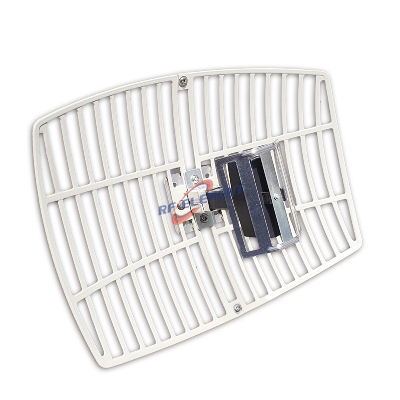
A 600 by 900 mm dual band parabolic grid antenna covering 2400 to 2500 MHz and 5150 to 5850 MHz, with 21 dBi on the low band and 22 dBi on the high band. The horizontal beamwidth is 12 degrees and the vertical beamwidth is 15 degrees, polarization is linear, VSWR is 1.8 or better, and the single N-Type female port carries 50 W. The reflector is an aluminium grid on a galvanized frame, the unit weighs 3.2 kg, and it mounts on a pole with the bracket supplied.
What the extra aperture buys
This panel is 0.54 square metres against 0.12 square metres on the 300 by 400 mm version. Four and a half times the area is 6.5 dB of theoretical gain, and the datasheet delivers 6 dB of it: 21 dBi against 15 dBi on the low band, 22 dBi against 16 dBi on the high band.
Six decibels has one meaning in a link budget. Range scales with the square root of gain, so 6 dB doubles the distance on the same path in free space. A 3 km hop becomes a 6 km hop with the same radios, the same power and the same channel width. That is the whole case for the larger panel, and it is worth checking against the cost of the mast and the wind loading before the order is placed.
A 5 km footprint in numbers
At 5 km the 12 degree horizontal beam covers about 1.05 km and the 15 degree vertical beam covers about 1.32 km at the half power points. That is a usable footprint for a point to multipoint access link where the far end is a small cluster rather than a single building.
Pointing is less forgiving than on the smaller panel. A one degree error at 5 km moves the beam centre by 87 m, and with a half power half angle of 6 degrees the margin is still comfortable, but the vertical axis is the one that catches installers out. On a sloping path the apparent elevation of the far end differs from the map bearing by more than a degree, so set the elevation on site with a received signal level reading rather than from the drawing.
| Frequency Range | 2400 – 2500 MHz | 5150 – 5850 MHz |
| Polarization | Linear | |
| Gain(dBi) | 21dBi | 22dBi |
| Horizontal Beamwidth | 12° | |
| Vertical Beamwidth | 15° | |
| Impedance | 50Ω | |
| VSWR | ≤ 1.8 | |
| Maximum Power | 50W | |
| Connector Type | 1 Port, N-Type Female | |
| Antenna Dimension(mm) | 600*900 | |
| Net Weight | 3.2kg | |
| Operating Temperature | -55° to +60° C (-67° to +140° F) | |
| Radome Material | Aluminum | |
| Mounting Options | Hanged on pole | |
The cost of VSWR 1.8
VSWR 1.8 is a return loss of 10.9 dB, which corresponds to a mismatch loss of 0.37 dB. In a link with 25 dB of margin that number does not matter. It matters when the same antenna is used as a receive only element in a low level front end, because the reflection also moves the noise match of the first stage.
The reason for the looser figure is the dual band feed. A single feed that has to work from 2400 to 5850 MHz cannot be perfectly matched at both ends, and the maker has chosen to hold the match at 1.8 rather than add a diplexer inside the housing. If a 1.5 figure is required on both bands, ask for the single band version of the same panel, which has one narrower matching network rather than two wide ones.
Wind load and pole sizing
The outline is 0.54 square metres. At 30 m per second the drag on that outline is about 360 N with a coefficient of 1.2, and the open mesh passes part of the airflow, so the real figure is lower than a solid dish of the same size. The datasheet does not quote a drag coefficient, so use the outline figure as a conservative estimate and check the pole clamp rather than the pole.
3.2 kg of mass matters less than the moment. Mount the centre of the panel within 300 mm of the clamp and use a 50 mm pole for a 6 km link on an exposed site. If the pole has to be taller than 6 m, add a stay rather than going up a pole size, because the bracket is the part that fails first.
Ordering
N-Type female is standard, the polarization is linear and vertical as shipped, and the frame suits a 40 to 50 mm pole. Samples in 3-5 days, production in 15-25 days.
If the hop is short and the mast is temporary, the 300 x 400 mm grid version halves the wind area and the weight for 6 dB less gain. If the link is 5 GHz only and the path needs more than 22 dBi, the 60 cm MIMO dish gives 30 dBi with two polarizations in a 5 degree beam. Single band panels and sector antennas for the same frequencies sit in the 5 GHz WiFi antenna range.
Send the path profile, the required availability and the pole height. The profile decides the Fresnel clearance, the availability decides the fade margin, and the pole height decides whether a grid or a dish is the right reflector for the site.
FAQ — Dual Band WiFi Parabolic Grid Antenna
What is the Dual Band WiFi Parabolic Grid Antenna used for?
What frequency band does the Dual Band WiFi Parabolic Grid Antenna cover?
What are the key specifications of the Dual Band WiFi Parabolic Grid Antenna?
Can RF element customize the Dual Band WiFi Parabolic Grid Antenna for my application?
What is the MOQ and lead time for the Dual Band WiFi Parabolic Grid Antenna?
How do I get a quotation for the Dual Band WiFi Parabolic Grid Antenna?