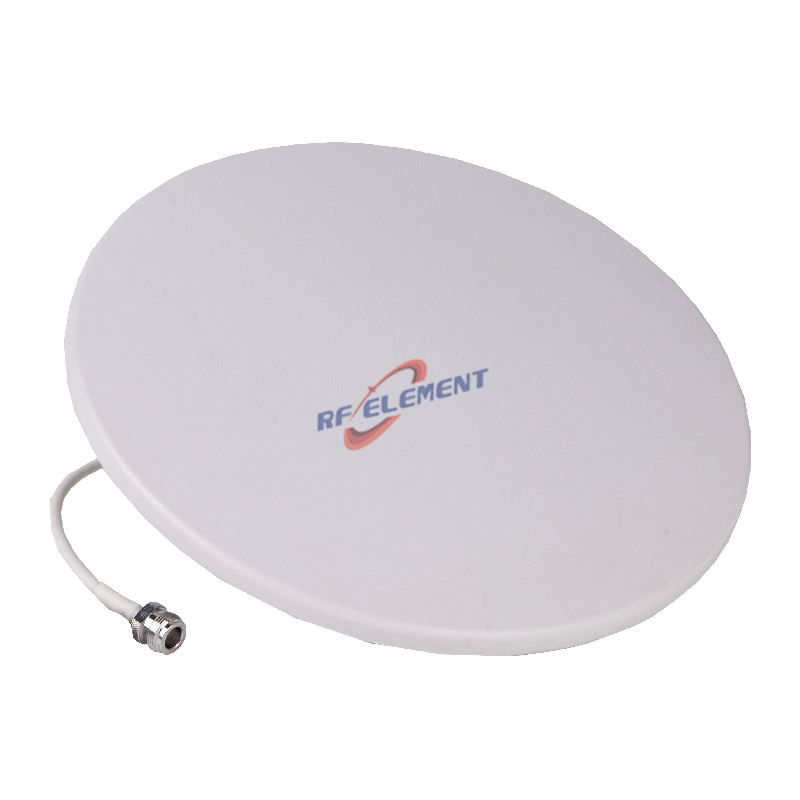
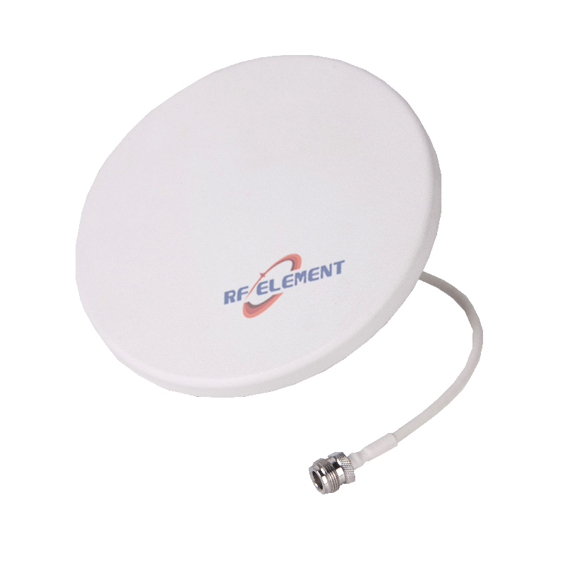
UHF Ceiling Antenna | Low Profile UHF Ceiling Antenna | 380-520MHz
Optimize your DAS with RF element's low profile VHF UHF ceiling antenna. Designed for 380-520MHz frequency bands, this ceiling mounted antenna ensures wide coverage and reliability. Get your quote now.
Specifications
A ceiling antenna covering 380 to 520 MHz in an 18 mm deep plate has to do three jobs at once: serve TETRA and public safety radio at the bottom of the band, private PMR in the middle, and LTE 450 plus UHF business radio at the top. The 1.37 to 1 bandwidth is the easy part. The two numbers that decide whether a floor actually gets covered are the vertical beamwidth, which this table does not publish but which can be calculated, and the spacing between antennas, which follows from that beam rather than from the gain figure. This page derives both, then covers the PIM question that a multi carrier distributed antenna system will ask.
Three sub-ranges, one plate, three different radiators
The table splits the band into 380 to 400, 400 to 450 and 450 to 520 MHz and gives 2, 2.5 and 3.5 dBi in that order. That progression is not marketing rounding: the 280 mm plate is 0.355 wavelengths across at 380 MHz and 0.485 wavelengths at 520 MHz, so the same piece of copper behaves like a different antenna at each end of the band. Gain from a fixed aperture rises roughly with the square of frequency, and 1.5 dB between the bottom and the top of the band is what that geometry supports.
The practical reading is that a link budget written at 390 MHz should not use the 3.5 dBi figure. Use 2 dBi at the bottom of the band and accept that the extra 1.5 dB only appears above 450 MHz. This is also why the antenna covers the three sub-ranges with one port: the matching network is designed to hold across the whole span, and the gain simply follows the aperture.
What the missing vertical beamwidth calculates to
The horizontal pattern is 360 degrees, and the vertical beamwidth is not listed, which is a gap in the table rather than in the product. It can be estimated from the gain. A directivity of 2 dBi is a factor of 1.58, so the beam solid angle is 4 pi divided by 1.58, which is 7.9 steradians; spread over a full 2 pi in azimuth, that gives a vertical beam of about 72 degrees. At 3.5 dBi the same arithmetic gives about 51 degrees. The beam narrows with frequency for the same reason the gain rises.
That estimate matters because it sets the ceiling height and the spacing. A 72 degree beam with its axis horizontal has its lower edge 36 degrees below the horizon, and from a 3 m ceiling it meets the floor about 4 m from the point under the antenna. At the top of the band the same calculation gives about 6 m. Beyond those radii the floor is lit by the skirt of the pattern rather than by the main beam, which is the region where coverage becomes uneven and where users report that a room works in one corner and not in another.
| Frequency Range | 380-520MHz | ||
| Frequency Sub-Range(MHz) | 380-400 | 400-450 | 450-520 |
| Polarization | Vertical | ||
| Gain(dBi) | 2 | 2.5±0.5 | 3.5±0.5 |
| Horizontal Beamwidth | 360° | ||
| Impedance | 50Ω | ||
| VSWR | ≤ 2.0 | ||
| Maximum Power | 50W | ||
| Connector Type | 1 Port, 4.3-10 Female or N-Type Female | ||
| Length | 280 mm | ||
| Width | 280 mm | ||
| Depth | 18 mm | ||
| Net Weight | 0.5 kg | ||
| Operating Temperature | -55° to +60° C (-67° to +140° F) | ||
| Radome Material | ABS | ||
| Radome Color | White | ||
| Mounting Options | fasteners and screws included for wall mounting | ||
Directly under a ceiling omni is the weakest point
A vertical omni radiates a torus, and the axis of that torus is a null. In a ceiling installation the null points at the floor immediately below the antenna, so the strongest coverage is a ring at a few metres radius, not the spot under the radome. This is counter intuitive in a room with a single antenna, where the installer expects the centre of the room to be the best served position.
The consequence for layout is that antennas are placed to overlap rings rather than to sit at the centre of each room. At 3 m ceiling height the ring falls between roughly 2 and 5 m from the axis, so a spacing of 6 to 8 m gives continuous coverage without putting the null over a workstation. In a corridor the geometry is better: the torus and the corridor axis line up, and one antenna covers a longer run than the same part covers in an open plan office.
One antenna for TETRA, PMR and LTE 450
The three sub-ranges map onto three different services. The 380 to 400 MHz segment is where TETRA and public safety networks sit in many European markets, 400 to 450 MHz carries private PMR, and 450 to 520 MHz covers UHF business radio and LTE 450. A distributed antenna system that has to carry all three would otherwise need three part numbers, three spares holdings and three installation drawings. One part that holds a VSWR of 2.0 across the whole span removes that overhead.
The power rating of 50 W is per port and well above what a DAS head end delivers per carrier, which is usually between 5 and 20 W. The limit that matters in a multi carrier system is not the antenna but the passive intermodulation produced by the connectors and the combiner, because two or more carriers in the same cable generate products that land inside the receive band. This table does not publish a PIM figure. For a single carrier system that is acceptable, since a match of 2.0 is enough. For a multi carrier DAS, ask for a PIM test report at the working power before the design is frozen.
Mounting, cable and the wall mount wording
The plate is 280 by 280 by 18 mm and weighs 0.5 kg, which fits a standard 600 by 600 mm ceiling grid with room to spare. The mounting row describes fasteners for wall mounting, while the product is a ceiling antenna, so the bracket type should be confirmed for a suspended tile ceiling rather than assumed: a tile bridge spreads the load and keeps the radome flush, while screws into a tile alone will not hold over time.
The connector is 4.3-10 female or N-Type female. At 400 MHz the cable loss is modest, about 1.5 to 2 dB for a 10 m run of RG58 class cable, so the choice between the two connectors is about PIM and mechanical robustness rather than loss. The 4.3-10 is the smaller and the more recent design and is the better choice where several carriers share the cable; the N-Type is the legacy interface that most existing DAS hardware still uses.
For a smaller room that only needs the 450 to 470 MHz band, a UHF ceiling antenna 450 to 470 MHz gives the same 3 dBi from a smaller plate. The wider UHF range is listed on the 450 MHz antenna category page, and the antenna selector tool compares ceiling, wall and outdoor versions of the same band.
Send the ceiling height, the services to be carried and the number of carriers to sales@rfelement.com, and we will confirm whether one antenna per room is enough or whether the ring geometry calls for two.
FAQ — UHF Ceiling Antenna
What is the UHF Ceiling Antenna used for?
What frequency band does the UHF Ceiling Antenna cover?
What are the key specifications of the UHF Ceiling Antenna?
Can RF element customize the UHF Ceiling Antenna for my application?
What is the MOQ and lead time for the UHF Ceiling Antenna?
How do I get a quotation for the UHF Ceiling Antenna?