5G Ceiling Antenna: Low-Profile vs. Conventional Solutions for Modern Connectivity
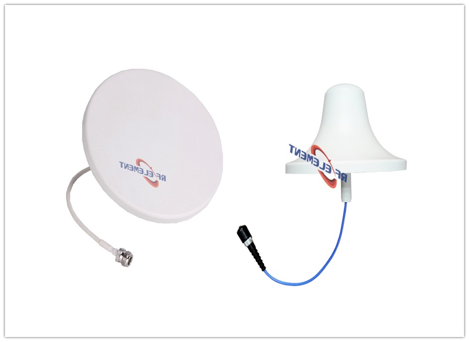
Indoor coverage projects usually start with one question: how much ceiling space can the antenna have? We build both answers at our ZhaoQing factory. Our slimmest 5G ceiling antenna measures 12 mm high with a 180 mm diameter; our conventional UHF ceiling antenna for 450-470MHz stands 98 mm tall with a 166 mm diameter. Between those extremes sit several more ceiling models covering 380-4200MHz, so the real decision is not "slim or nothing" — it is choosing the right housing for the radio plan, the ceiling type, and the PIM budget. This page compares the two families with the actual numbers from our catalogue, not marketing rounds.
What counts as low-profile in our catalogue
We ship three low-profile ceiling models that show the range clearly.
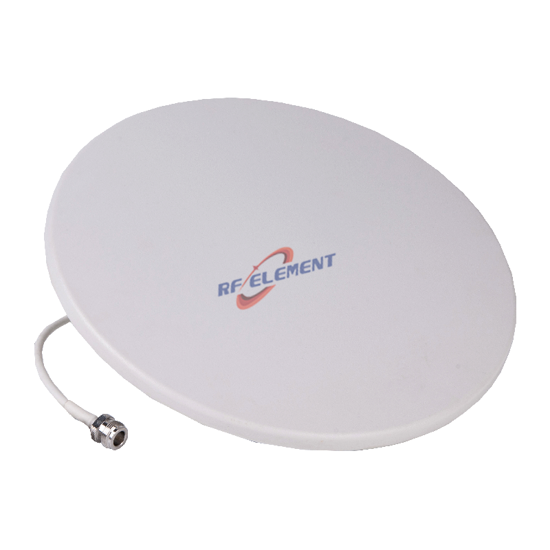
Compact 5G Ceiling Antenna, 698-4200MHz. The housing is 180 mm across and 12 mm high, weighing 0.3 kg. Gain rises with frequency: 1.5 dBi across 698-806 MHz, 2.2 dBi across 806-960 MHz, 3.5 dBi across 1350-1550 MHz, 4.5 dBi across 1710-2700 MHz, and 5.5 dBi across both 3300-3800 MHz and 3800-4200 MHz. VSWR stays at or below 1.5 on the low and mid bands and at or below 1.6 at the top of the range. With 2×20 W carriers the third-order PIM reads -153 dBc, power handling is 50 W, and the single port accepts 4.3-10 female or N-type female. Operating temperature spans -55° to +60° C.
Low PIM low-profile antenna, 698-3800MHz. The radome is 186 mm in diameter and 15 mm high, again 0.3 kg. Gain is 2.5 dBi below 960 MHz and 4.0 dBi above 1710 MHz, with VSWR at or below 1.8 and 1.5 respectively. PIM is rated -150dBc at 2×43 dBm, and the connector is a single 4.3-10 female port.
4x4 MIMO slim ceiling antenna, 698-4200MHz. Same frequency span, four RF ports, 385 mm diameter and 13 mm high, 1.3 kg. The per-band gains match the compact model (1.5 to 5.5 dBi), and the 4x4 arrangement can raise 4G/5G data rates up to four times what a single port delivers, which is why DAS integrators pick it for high-density floors.
All three keep the radiation pattern omnidirectional at 360°, with elevation beamwidths from 90±10° down to 40±20° depending on the sub-band.
What the conventional side looks like
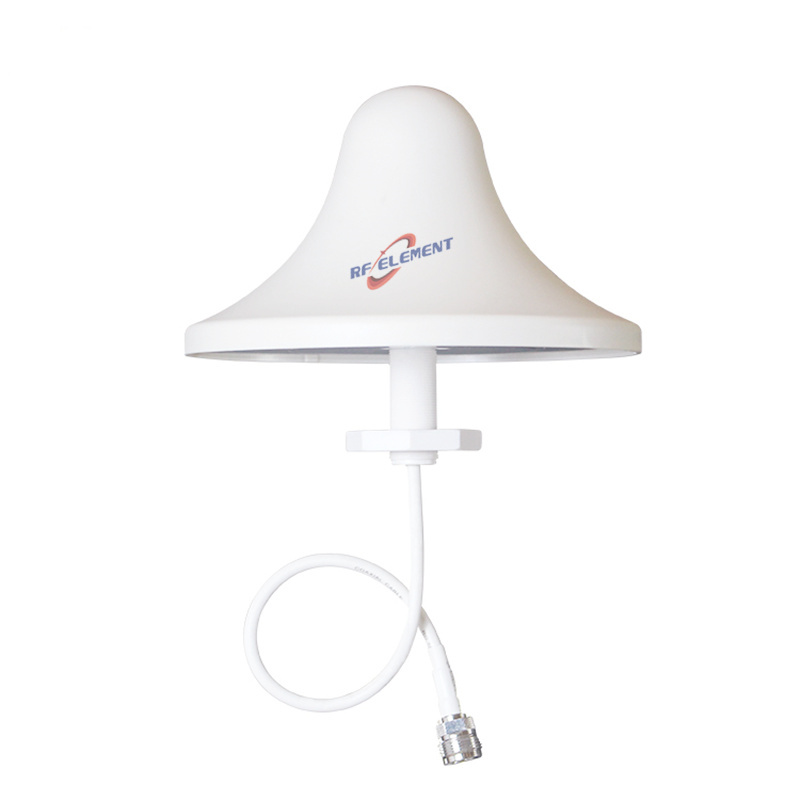
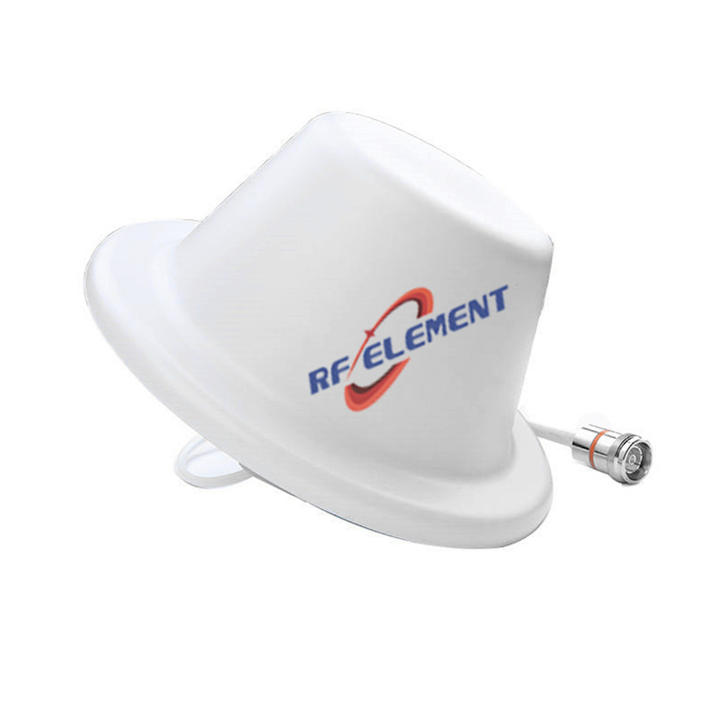
Conventional ceiling housing trades slimness for cost and, at UHF, for real estate. Our UHF ceiling antenna for 450-470MHz delivers 3 dBi gain, 50 W, VSWR at or below 1.5, and an N-type female port inside a 166 mm × 98 mm housing weighing 0.5 kg. The taller dome simply gives the 450-470 MHz element room to work; physics does not offer that radiation aperture in a 12 mm disc.
Our wide-band ceiling antenna covering 380-3800MHz is the middle path: 280 mm across and 18 mm high, 0.5 kg, gain from 1.5 dBi at 380-400 MHz up to 5 dBi at 3300-3800 MHz, with VSWR between 2.0 at the extremes and 1.5 mid-band. One port, 4.3-10 female or N-type female.
When a zone needs direction rather than all-around coverage, we move off the ceiling: the 5G n78 MIMO panel antenna covers 3300-3800 MHz with 12 dBi gain, 65° horizontal and 28° vertical beamwidth, two N-type ports, in a 239 × 190 × 35 mm enclosure at 1.0 kg.
The differences that actually matter
Gain ceiling. A 12 mm disc cannot out-gain a deep dome at the same frequency. Both families land between 1.5 and 5.5 dBi on the shared bands, but the conventional housings hold their gain curve further down — the wide-band model still delivers 2.5 dBi at 400-698 MHz, where most low-profile designs have already stopped. If the link budget needs 12 dBi or a 65° beam, neither ceiling family is the tool; that is panel territory.
PIM budget. Every low-profile model above carries an explicit PIM rating: -153 dBc for the compact and 4x4 units at 2×20 W carriers, -150dBc at 2×43 dBm for the 698-3800 MHz model. In a shared DAS where 20-40 W carriers from multiple operators mix at the antenna, that number decides whether the downlink stays clean.
Ports and MIMO. One port on the compact and wide-band units, four on the 4x4 slim, two on the n78 panel. The 4x4 slim needs the 385 mm face to fit four radiators with 25-30 dB port-to-port isolation; the isolation figures are 15 dB or higher on the low bands and 22 dB at 3300-3800 MHz.
Weight and mounting. 0.3 kg versus 0.5-1.3 kg rarely changes the mount, but it does change what a suspended-ceiling tile tolerates. All models share the same -55° to +60° C rating.
Where a low-profile antenna is the wrong choice
The project needs UHF 450-470 MHz coverage on a tight budget: the 98 mm conventional dome is the honest answer, because the physics of that band does not fit a 12 mm disc.
The zone needs directional coverage along a corridor, tunnel section, or perimeter: a 65° panel at 12 dBi will beat any omni ceiling unit per rupee spent.
The ceiling is exposed industrial trusswork where nobody sees the antenna: paying for radome aesthetics buys nothing.
Where a conventional housing is the wrong choice
Hotels, conference centres, and flagship retail, where the ceiling is part of the interior design: a 98 mm dome at every 15 m bay draws complaints that a 12-15 mm disc never will.
Suspended ceilings with under 20 mm of clearance above the tile: the compact and low-PIM models are the ones that physically fit.
DAS builds with a strict PIM specification: start from the units with published -150 to -153 dBc figures rather than unlisted housings.
Frequency planning notes
Both families cover the 5G bands that matter indoors today: 1710-2700 MHz for mid-band LTE and n41-class deployments, and 3300-3800 MHz for n78. The compact model extends to 3800-4200 MHz for regions that licence the upper edge. Below 1 GHz, the wide-band conventional unit reaches 380 MHz, while the low-profile group starts at 698 MHz — if the site still carries legacy 450 MHz services, plan a separate UHF dome rather than forcing one housing to do both.
Ordering, samples, and what we send you
We manufacture the whole range in-house at ZhaoQing and support OEM/ODM changes — connector type, cable length, mounting hardware, radome colour, and re-tuned gain or beamwidth on the same mechanical platform. Sample units ship from stock within 3-5 working days for pilot builds, while volume runs are scheduled at 15 to 25 working days, with low MOQ so you can move from pilot to rollout without switching supplier. Email sales@rfelement.com with your band plan, target gain, port count, and ceiling constraints, and we will reply with the matching model, the full specification table, mechanical drawings, and sample units. If you tell us the mounting ceiling type and the carrier mix, we will also flag the PIM figure you should hold the installation to.
TAG:5G Ceiling Antenna: Low-Profile vs. Conventional Solutions for Modern Connectivity https://www.rfelement.com