5G Directional Antenna Production Using CNC Punching Machines
A directional antenna is a flat plate that learned to aim. The pattern, the gain and the port-to-port isolation on the datasheet are consequences of geometry that a punching machine produced, and the tolerance it held is the reason two units built to the same drawing behave the same way on a mast in different weather. We run punching, casting and machining side by side in the same plant, so what follows is a description of where each process earns its place rather than an argument for one of them.
The base plate is an electrical part made mechanically
Everything the RF engineer cares about lives in the plate. Hole positions set element spacing, and a shift of a few tenths of a millimetre moves the phase across the aperture. Flatness decides how much the reflector warps once the connectors are torqued down, which is how a plate that measures well on a bench still detunes after it is bolted to a mast. Threads and countersinks are cut in the same setup whenever the tooling allows, because every additional handling step is another chance to lose the datum the next operation depends on. This is the part of antenna production that never appears on a datasheet and surfaces instead as unit-to-unit variation in the field, usually blamed on the radio.
What punching does well
Sheet metal is the fastest route from a drawing to a finished radiator. A turret punch works from a digital program, so a revision costs a new file rather than a new tool, and a first article can reach inspection within days of drawing release instead of weeks. The process handles mild steel, stainless, aluminium and copper without changing the machine, which matters when one project needs stainless for corrosion resistance and the next wants aluminium for weight. Once the program is proven, throughput is set by the sheet handler rather than the punch head, so growth in volume rarely demands a different process. It demands a tighter nest, a better turret layout and less scrap between parts. Nest utilisation is the number that quietly decides the piece price, and on a plate with generous margins it is often possible to recover a fifth of the sheet by redistributing the blanks.
The surface treatment is part of the tolerance
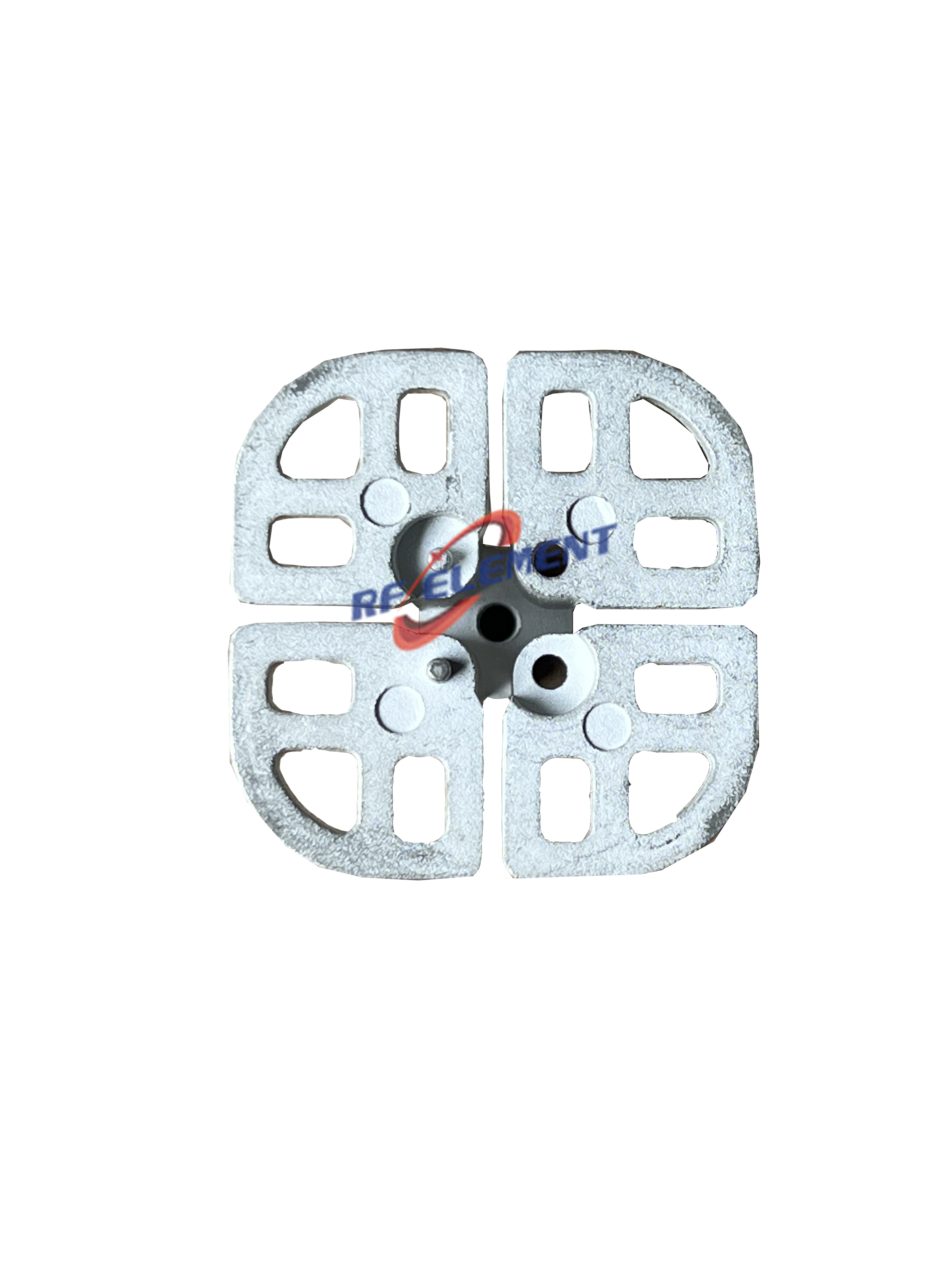
Plating and blasting are not decoration. On our die-cast parts the finish is sandblasting followed by electroplating, and that sequence changes dimensions as well as appearance. A die-cast element covering 698-960 MHz leaves the line at 73 mm square by 93 mm tall and 80 g, a 3300 to 3800 MHz element sits at 33 mm square by 23 mm tall and 7 g, and a 5 GHz die-cast part measures 22 mm square by 15 mm tall at 5 g, all carrying the same treatment and the same white finish. The deposit is part of the electrical stack, not a cosmetic layer, because skin depth at 5.8 GHz is measured in hundredths of a millimetre and a thin coating behaves as resistance rather than conductor. That is the reason we specify the finish on the drawing instead of leaving it to a plating shop's default thickness.
Where CNC punching is the wrong choice
Punching loses the moment the geometry stops being flat. A die-cast element at volume costs less per part than a punched one, because the tool cost spreads across thousands of shots and the casting carries its mounting bosses and draft angles in the same cycle. A waveguide interface is a separate problem again: the WR62 throat on our WR62 microwave panel has to be machined, since the internal dimensions set which mode propagates and a punched aperture would not hold them. Cast housings are outside the process as well, and they are usually the right answer for a sealed outdoor unit. Extrusion is the third case: a length of aluminium profile carries a constant cross-section that no flat blank can imitate, and the tooling is a die rather than a punch and a brake. If a part must be bent and then plated without moving, the sequence needs planning before the first blank is cut, not after the fixture is built.
Material choice follows the process, not the datasheet
Sheet gauges behave differently once they are formed, and that catches projects that specify a material by name and a process by habit. Aluminium is the default for outdoor plates because it is light and takes a chromate or anodised finish, but it springs back further than steel, so the bend allowance has to be measured on the actual alloy rather than inherited from a table. Stainless holds its shape and resists salt at roughly three times the weight, and it wears tooling faster, which shows up as burr on the punch edge before it shows up in the part. Copper and its alloys are chosen for conductivity in feed structures, and they work-harden, so a second forming pass on copper is a different operation from the first. The workable rule is that the environment picks the material and the geometry picks the process. A plate that needs three bends and a plated finish is a punching job; the same plate with a waveguide throat added to it is not.
What the rest of the assembly asks for
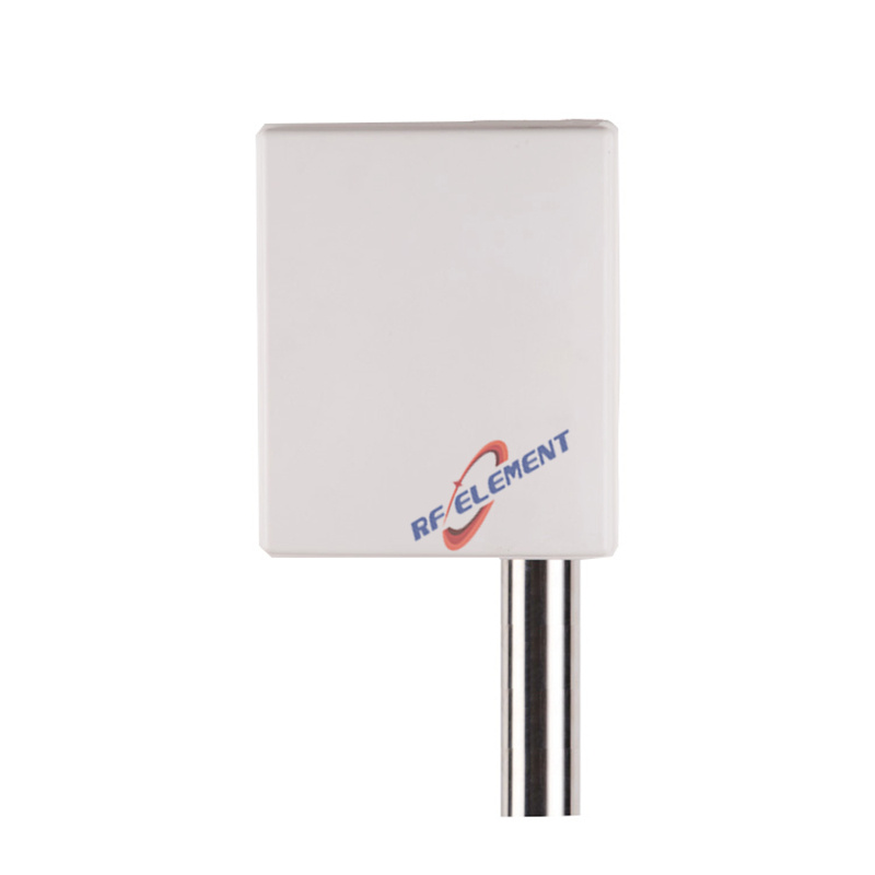
A plate is only half an antenna, and the numbers on the finished unit come from the pair. Our 3.5 GHz n78 panel pairs 12 dBi with a 65 degree horizontal and 28 degree vertical pattern inside a body 239 mm wide, 190 mm tall and 35 mm deep at 1.0 kg, while the 5 GHz wireless bridge panel reaches 18 dBi over 30 by 20 degrees from a 305 by 305 mm plate 25 mm deep, seated in a cast housing with a 220 mm square footprint and 60 mm of depth. Both depend on hardware somebody has to make: an adjustable antenna mounted pole offering 120 degrees of tilt adjustment, a 35 mm tube section, 220 mm of reach and a 0.8 kg body in aluminium or steel. The narrower the pattern, the more that mount matters, because the same two degrees of sag costs far more pointing error on a 20 degree beam than on a 65 degree one.
Inspection is where the process proves itself
We check the first article against the drawing and then check the running parts against the first article, because that second comparison is what catches tool wear and spring-back while the order is still recoverable. Port positions, plate flatness, thread depth and plating thickness are measured before the plates are married to their radomes, and the measurements are recorded against the batch rather than against the job. Parts that fail usually fail in the same place: a corner that took one more handling step than the rest of the plate, or a hole punched after a bend instead of before it. A single-port 5G panel weighing 0.4 kg shows how little material a well-planned nest needs, because most of its 45 mm of depth holds nothing but air reserved for the connector body and the matching network.
What to send us
Send the plate drawing with the datum called out, the annual volume, the material and the finish you need, plus the tolerance band the RF design can really live with. Mail all four to sales@rfelement.com; the quotation that comes back will identify the process rather than a machine model. If the antenna is still being modelled, say so, because the process choice is cheaper to make before the pattern is frozen than after the first prototype has been measured.
TAG:5G Directional Antenna Production Using CNC Punching Machines https://www.rfelement.com