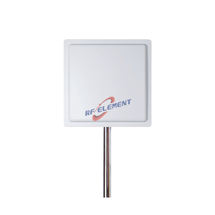
13GHz Microwave Panel Antenna | High-Gain Microwave Directional Antenna | RF element
Specifications
A 13 GHz panel antenna with 28 to 30 dBi and a 5 by 3.5 degree beam is a point to point part, not a coverage antenna. The numbers that decide whether a link closes are the aperture efficiency behind those 28 dBi, the 7 dB of extra free space loss that 13 GHz carries compared with 5.8 GHz, and the rain margin that has to be added on top. This page works through the geometry at one kilometre, reads the gain against the 340 mm panel, explains what the WR62 interface means at the radio end, and covers the aiming and wind load details that matter on a mast.
What a 5 by 3.5 degree beam covers at one kilometre
At 13 GHz the free space wavelength is 300 divided by 13.05, which is 23 mm. A beam 5 degrees wide in azimuth and 3.5 degrees in elevation opens to 87 metres by 61 metres at one kilometre. One degree of azimuth error moves the centre of that rectangle 17 metres sideways at the same distance, so the aiming tolerance is set by the beam, not by the mount.
That geometry is the reason a 13 GHz path is surveyed rather than installed by eye. At 300 metres the same beam is 26 by 18 metres, which tolerates a mast that leans a little. At 3 kilometres it is 262 by 184 metres, and a 2 degree error puts the far end outside the main lobe. A link that works at 500 metres and fails at 2 kilometres is usually an aiming problem before it is a gain problem, and the cure is a finer alignment step and a signal reading at both ends rather than a larger antenna.
Reading 28 to 30 dBi against a 340 mm panel
The 41253 rule divides 41253 by the product of the two half power beamwidths. For 5 by 3.5 degrees the product is 17.5, which gives a directivity of 2357 in linear terms, or 33.7 dBi. The datasheet range of 28 to 30 dBi therefore sits 3.7 to 5.7 dB below the ideal pattern, which is an aperture efficiency between 23 and 36 percent.
That is a normal range for a flat panel with a radome and a printed feed, but it is worth understanding where the loss goes. At 13 GHz the 340 mm square is 14.8 wavelengths on a side, and a fully illuminated aperture of 0.116 square metres would produce 34.4 dBi. The 4.4 to 6.4 dB between that figure and the stated gain is split between the taper of the illumination, the spill past the edges and the dielectric of the cover. None of it is waste that a buyer can recover by asking for a different number; it is the trade a low profile panel makes against a dish of the same size.
The same arithmetic is useful on a competitor sheet. A 13 GHz panel claiming 34 dBi from a 5 by 3.5 degree pattern would have to be over 100 percent efficient, which is not possible. Either the beam is narrower than stated or the gain is optimistic by 4 dB, and both are worth a question before the order.
| Frequency Range | 12.7-13.4GHz | |
| Polarization | Vertical | |
| Gain(dBi) | 28-30dBi | |
| Horizontal Beamwidth | 5° | |
| Vertical Beamwidth | 3.5° | |
| Impedance | 50Ω | |
| VSWR | ≤ 1.8 | |
| Maximum Protection(W) | 1000W | |
| Connector Type | 1Port, WR62 | |
| Antenna Dimension(mm) | 340*340*30 | |
| Net Weight | 2.5 kg | |
| Operating Temperature | -55° to +60° C (-67° to +140° F) | |
| Radome Material | ABS | |
| Radome Color | White | |
| Protection Rating | IP65 | |
Why 13 GHz is chosen for spectrum, not for reach
Free space loss at one kilometre is 114.7 dB at 13 GHz and 107.7 dB at 5.8 GHz, so the higher band starts 7 dB behind. Gain moves the other way. The same 340 mm panel that gives 28 to 30 dBi at 13 GHz gives about 23 dBi at 5.8 GHz, because gain from a fixed aperture rises with the square of frequency. The two effects very nearly cancel, which is the honest way to describe the choice: 13 GHz does not reach further from the same box, it reaches the same distance in a band where the channel is cleaner and the antenna is smaller for a given gain.
Rain has to be added explicitly. At 25 mm per hour the specific attenuation is of the order of 0.6 to 0.8 dB per kilometre at 13 GHz against roughly 0.1 dB per kilometre at 5.8 GHz. On a 2 km path that is an extra 1.0 to 1.4 dB in heavy rain, which belongs in the fade margin rather than in a service call. Terrain clearance is the other item. The first Fresnel zone at 1 km has a radius of 2.4 m at this frequency, and 60 percent of it, about 1.4 m, is the clearance a path survey should confirm along the whole route.
The WR62 interface and what the 1000 W rating means
The connector listed is WR62, not a coaxial type. WR62 is a rectangular waveguide with a band from 12.4 to 18 GHz, so 12.7 to 13.4 GHz sits comfortably inside it with no risk of the next mode being excited. The practical consequence is that the radio has to present a waveguide flange, or a coax to waveguide transition has to be added, and that transition is a real component with its own loss and its own mechanical length.
Loss in the run between radio and antenna deserves more attention than the antenna itself. A metre of WR62 costs a fraction of a decibel, while a metre of flexible coaxial cable of the LMR-400 class is around half a decibel at 13 GHz, and a thin jumper is worse. Two metres of thin coax can cost 3 dB, which is half the gain of the panel, so the radio belongs at the back of the antenna with a short waveguide run rather than at the bottom of the mast.
The 1000 W figure in the table is a protection rating for the antenna, far above the 1 to 10 W that a 13 GHz link radio delivers. It should not be read as a working power level, and it is not a substitute for checking the radio datasheet before a long cable run is designed around the wrong assumption.
VSWR 1.8, aiming and wind load on the mast
A VSWR of 1.8 is a reflection coefficient of 0.286, a return loss of 10.9 dB and a mismatch loss of 0.37 dB. Across 12.7 to 13.4 GHz, a band 5.5 percent wide, the match is normally best in the middle and reaches the stated figure at the edges, so 0.37 dB is the number to enter in a link budget rather than a typical mid band value.
The panel measures 340 by 340 by 30 mm and weighs 2.5 kg. Its frontal area of 0.116 square metres produces about 110 newtons at 40 metres per second before any shape factor is applied, which a standard mast clamp will take. The part that needs care is the joint between the clamp and a 30 mm deep box, because the lever arm is short and the panel is wide, so a bracket that spreads the load across the back plate is better than one that grips a single point.
The radome is ABS, the protection rating is IP65 and the operating range runs from minus 55 to plus 60 degrees Celsius, so the mechanical limits are wider than those of the radio behind it. For a path where 13 GHz is not licensed or where the distance is set by terrain, a 5 GHz parabolic dish antenna covers the same job with a wider beam and a larger aperture. The rest of the range is listed on the RF product range page, and the antenna selector tool filters by frequency, gain and pattern shape.
Send the path length, the required availability and the radio output to sales@rfelement.com, and we will return a link budget with the rain margin shown separately from the antenna gain.
FAQ — 13GHz Microwave Panel Antenna
What is the 13GHz Microwave Panel Antenna used for?
What frequency band does the 13GHz Microwave Panel Antenna cover?
What are the key specifications of the 13GHz Microwave Panel Antenna?
Can RF element customize the 13GHz Microwave Panel Antenna for my application?
What is the MOQ and lead time for the 13GHz Microwave Panel Antenna?
How do I get a quotation for the 13GHz Microwave Panel Antenna?