The Role of Advanced Wide Band Beamwidth Spotlight Antennas
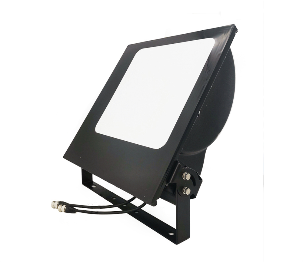
Two 65-degree sector panels bolted to a street lamp used to be the standard answer for covering a new residential tower. We know because our customers keep replacing them. The unit that replaces the pair is a wide band beamwidth spotlight antenna we build in Zhaoqing: one enclosure, three sub-bands from 806 to 3800 MHz, and a horizontal beam that is roughly a third of a conventional sector panel's. This article explains what the design does, where it earns its keep, and equally important, where you should not use it.
Why the 65-degree playbook breaks above the fourth floor
A standard cellular sector panel carries a horizontal half-power beamwidth of about 65 degrees, and that geometry works well when the users it serves are spread horizontally across a district. High-rise housing inverts the problem. Floors stack vertically along a narrow building face, so much of a 65-degree fan never touches an occupied floor. The common workaround is mounting two panels at different tilts on the same pole, which doubles the feeders, the connectors, and every passive junction between radio and air, and each junction is a place where signal and PIM both get worse.
Long feeder runs make it worse. On a rooftop or lamppost installation the antenna often sits tens of meters from the radio room, and lossy cable at high sub-band frequencies eats exactly the margin that in-building coverage needs. The symptoms arrive as dropped calls on upper floors and congestion complaints at evening peak, not as a failed site acceptance test, which is why the pattern survives in older networks.
What the spotlight geometry changes
Our spotlight unit puts the energy where high-rise users actually are. The published numbers, taken directly from the product's specification table:
Frequency coverage in three sub-bands: 806-960 MHz, 1710-2700 MHz, and 3300-3800 MHz
Gain of 9 ±1 dBi on the low band, 11 ±1 dBi mid, and 13 ±1 dBi on 3300-3800 MHz
Horizontal beamwidth of 35 ±5°, 28 ±5°, and 22 ±5° on those three sub-bands respectively
Vertical beamwidth of 65 ±5° low, 55 ±5° mid, and 40 ±5° high
Dual-polarized ±45°, 50 ohm feed, VSWR ≤ 1.8 across the range
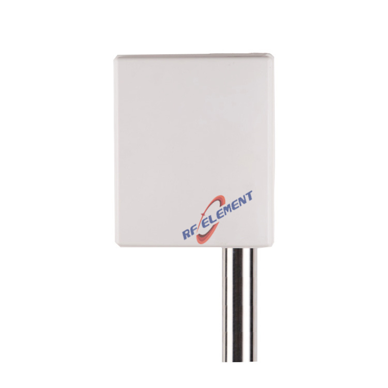
Compare that with a conventional panel: our own 698-3800 MHz 2x2 MIMO panel, a typical sector unit, runs a 65 ±15° horizontal beam. The spotlight's 22-35 degrees concentrates the same transmit power into a narrower horizontal slice while keeping a tall vertical beam, so a single antenna on one building face can light up a tower from podium to roof. The sub-band gain steps also match the physics: 11 ±1 dBi across the crowded 1710-2700 MHz mid band gives the tall pattern its reach, while 13 ±1 dBi at 3300-3800 MHz adds the margin that high-band 5G needs on a long feeder run. In practice one unit replaces the two-panel stack, which removes a full set of feeders and connectors from the link and recovers much of what line and road losses were eating.
Why the enclosure matters as much as the pattern
Sites in residential areas get rejected by residents, not by engineers. The spotlight antenna ships in a black UPVC radome shaped like a landscape spotlight, 430 x 420 x 135 mm and 4 kg, which mounts on a wall or pole the way outdoor lighting does. Tenants photograph lamp brackets, not antennas, and planning discussions that once stalled get signed. That is the camouflage half of the product, and for DAS (Distributed Antenna System) operators working campus and building contracts it is often the difference between a site that gets built and one that gets appealed.
Electrical durability is specified for outdoor duty: 100 W maximum input power, front-to-back ratio ≥ 20 dB, third-order PIM of -150 dBc at 2 x 2 W carriers, and an operating range of -55° to +60° C. Both feed ports land on 4.3-10 female or N-type female connectors, so integrators can match whatever the DAS combiner on site uses. The PIM figure deserves a note. In a DAS deployment the same infrastructure serves many carriers, so the antenna sits close to high-power combined signals, and passive intermodulation products that land in a receive band cannot be filtered out downstream. Keeping the antenna itself rated at -150 dBc means integrators do not inherit a PIM problem at the last meter of the chain.
Where the spotlight antenna is the wrong choice
We sell this unit happily and we still talk customers out of it regularly, because three scenarios call for something else:
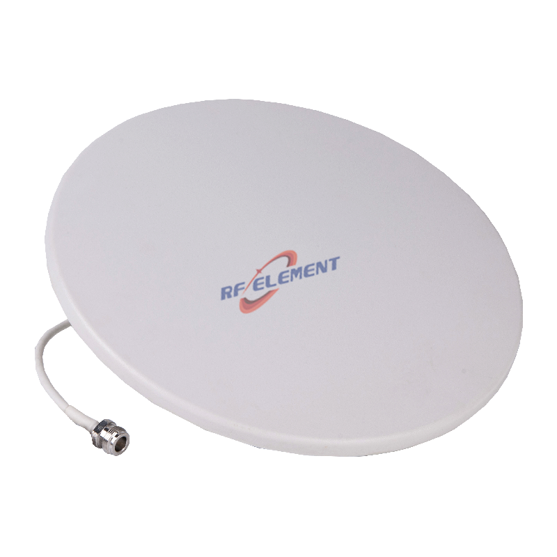
Indoor coverage. A wall-mounted directional unit on a building face does nothing for the lobby, the basement car park, or the elevator shaft. Those need omnidirectional ceiling units; our wide band ceiling antenna covers 380-3800 MHz with a 360° horizontal pattern, gains from 1.5 to 5 dBi depending on sub-band, and an 18 mm profile that disappears into the ceiling grid at just 0.5 kg.
Point-to-point and backhaul links. Narrow horizontal beamwidth for area coverage is the wrong tool for a fixed link between two towers. A long-haul microwave link wants a pencil beam and high gain, which is what our 13 GHz microwave panel antenna delivers, 28-30 dBi with a 5° by 3.5° beam at 12.7-13.4 GHz.
Wide-area district coverage at street level. If the users spread across a district instead of stacking in a tower, the conventional 65° or 90° sector panel remains the right geometry, and the spotlight's narrow fan would simply leave streets uncovered.
What to send us when you inquire
The fastest path to a useful answer is a coverage sketch rather than a part number: the building height, the mounting face you have available, the bands you need to serve, and the distance from radio to antenna. Our engineering team retunes gain and beamwidth on the same mechanical platform when a project needs it, sample lead time is 3-5 working days and mass production 15-25 working days, and we ship evaluation units to buyers who want to measure before committing. Send the sketch to sales@rfelement.com and we will come back with a mounting plan and the full measured dataset.
TAG:The Role of Advanced Wide Band Beamwidth Spotlight Antennas https://www.rfelement.com