2.4GHz Panel Antenna | WiFi Flat Panle Antenna | 18dBi
Specifications
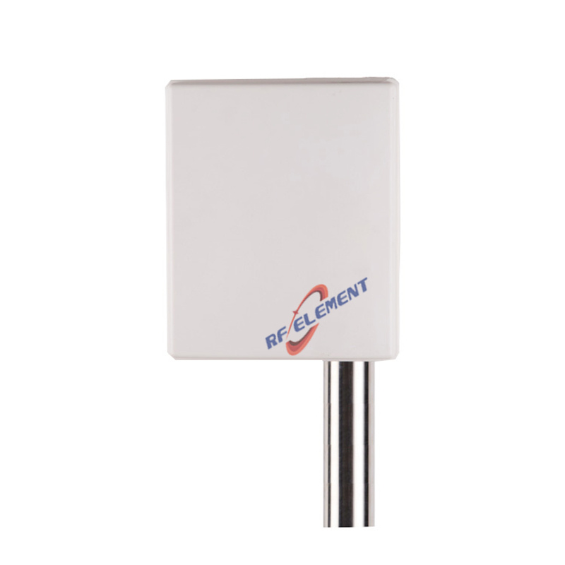
An 18 dBi flat panel for 2.4 GHz point-to-point and long range multipoint links, built on a 305 x 305 x 25 mm plate weighing 2.0 kg. The horizontal beam is 22 degrees wide and the vertical beam 20 degrees, so the antenna concentrates power into a narrow forward cone. VSWR is at or below 1.5 across 2400-2500 MHz, maximum power is 50 W, and the single output is an N-Type female connector.
What 18 dBi buys and what it costs
Eighteen decibels is roughly 6 dB more than a 12 dBi panel, which doubles the usable distance in free space and quadruples it in a link where both ends are upgraded. The cost is angular tolerance. A 22 degree horizontal beam covers about 39 m of width at 100 m, 194 m at 500 m and 388 m at 1 km, so a two degree aiming error moves the coverage edge by 35 m at a kilometre.
That tolerance is the practical limit on this antenna. On a short link of 200 m, a 22 degree beam is easy to aim and the extra gain is free. On a 3 km link the same beam has to be aligned with a survey bearing and checked with a signal meter, because the difference between boresight and a two degree error is several dB of received level.
Fresnel clearance matters more than gain
At 2.4 GHz the first Fresnel zone at mid-path is about 8.6 m in radius on a 1 km link. If more than 40 percent of that zone is obstructed, the path loss rises faster than the antenna gain can compensate, and upgrading from 14 dBi to 18 dBi will not fix the link. Check the profile before specifying the antenna, and raise the mounting point rather than buying more gain.
This is also why the 25 mm depth is useful: the flat plate can be mounted close to a mast surface without a long standoff, which makes it easier to get the height the Fresnel zone needs on a crowded pole.
| Frequency Range | 2400-2500MHz | |
| Polarization | Vertical | |
| Gain(dBi) | 18 | |
| Horizontal Beamwidth | 22° | |
| Vertical Beamwidth | 20° | |
| Impedance | 50Ω | |
| VSWR | ≤ 1.5 | |
| Maximum Power | 50W | |
| Connector Type | 1Port, N-Type Female | |
| Antenna Dimension(mm) | 305*305*25 | |
| Net Weight | 2.0 kg | |
| Operating Temperature | -55° to +60° C (-67° to +140° F) | |
| Radome Material | ABS | |
| Radome Color | White | |
| Mounting Options | Pole mounting | |
Vertical beam and site-to-site consistency
A 20 degree vertical beam at 20 m height covers the ground from about 55 m outward. If the subscriber units in a multipoint network are at different distances but similar heights, that is a comfortable footprint. If some are close to the mast and low, they fall inside the near-field gap and will need a separate antenna or a different mounting height.
For a repeated design across many sites, keep the mounting height and downtilt identical. A 20 degree beam is narrow enough that a 3 m difference in height changes the inner edge of coverage by roughly 8 m, which is visible in a drive test.
Polarisation and interference
The single port is vertically polarised. In a point-to-point link, both ends must use the same polarisation; mixing a vertical panel with a horizontal one costs 20 dB or more of cross-polar discrimination and the link will appear to have far less margin than the calculation predicts.
For multipoint base stations serving client radios with unknown orientation, vertical is the usual default because most access points and client devices use vertical elements. Where the site is congested, a 22 degree beam also rejects much of the interference arriving from the sides, which is a benefit that does not appear in the gain figure.
Mounting
The plate fixes to a pole with the bracket supplied. At 2.0 kg the load is modest, but the 305 mm square face is a wind sail: clamp at two points on the bracket and keep the plate at least 200 mm from the pole surface, because a metal mast inside the near field distorts the pattern and can shift the boresight by several degrees.
Seal the N-Type connector with self-amalgamating tape and provide a drip loop. On a 2.4 GHz link the connector is usually the first point of water ingress, and a corroded joint looks exactly like a radio fault in the RSSI graph.
Ordering
N-Type female is standard, with radome colour and packing quantity confirmed at order. Samples in 3-5 days, production in 15-25 days.
Where the link is shorter and the aiming tolerance needs to be wider, the 14 dBi 2.4 GHz panel antenna uses a 35 degree beam in a 0.9 kg housing. For a multi-sector base station rather than a single link, the 90 degree 2.4 GHz MIMO sector antenna covers a wider azimuth with two polarisations.
Send the link distance, the mounting heights at both ends and the required availability. Those three numbers decide whether 18 dBi is the right gain or whether the path needs a different height instead.
FAQ — 2.4GHz Panel Antenna
What is the 2.4GHz Panel Antenna used for?
What frequency band does the 2.4GHz Panel Antenna cover?
What are the key specifications of the 2.4GHz Panel Antenna?
Can RF element customize the 2.4GHz Panel Antenna for my application?
What is the MOQ and lead time for the 2.4GHz Panel Antenna?
How do I get a quotation for the 2.4GHz Panel Antenna?