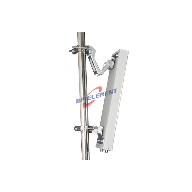
Dual Band WiFi Sector Antenna | 2.4GHz/5.8GHz 16dBi
Specifications
The four port count on this dual band sector antenna is the specification most often misread. Two ports serve 2400 to 2500 MHz and two serve 5720 to 5850 MHz, one pair per band carrying horizontal and vertical polarization, so the radio sees 2x2 MIMO on each band rather than 4x4 on either. That distinction decides which access point the antenna can be paired with, and it is worth settling before the bracket is ordered. The rest of this page covers where 14 and 16 dBi come from inside a 980 mm radome, why the two bands have different horizontal beamwidths, and what a 3.5 kg panel one metre long asks of the mast.
Four ports do not mean 4x4: how the two bands are paired
The specification lists polarization as horizontal plus vertical, with four N-Type female ports and two gain figures. The only arrangement that produces those numbers is one horizontal and one vertical port per band. A radio with two 2.4 GHz chains and two 5.8 GHz chains connects directly and gets 2x2 on both bands. A radio with four chains on a single band cannot use this antenna as a 4x4, because two of its ports are tuned to the other band and will present a high VSWR outside their range.
The practical check is to count the radio ports per band before ordering. A dual band access point with four chains split two and two is the intended match. A single band 4x4 radio needs a single band antenna with four ports in one band, and no amount of port counting on this product will make it fit. Getting this wrong is expensive because the antenna is mechanically correct and will mount, and the fault only shows up as two chains that will not associate.
980 mm of aperture sets both gains
At 2450 MHz the wavelength is 122 mm, so the 980 mm radome is 8 wavelengths long. At 5785 MHz the wavelength is 52 mm, so the same radome is 19 wavelengths. The vertical beamwidth follows the aperture directly: 15 degrees at 2.4 GHz and 7 degrees at 5.8 GHz, a ratio of 2.14 against a frequency ratio of 2.36. Those two numbers being close is the evidence that the vertical pattern is set by length rather than by the feed design, and it is the reason the gain rises from 14 to 16 dBi instead of staying flat.
The horizontal beamwidth moves the other way, from 65 degrees at 2.4 GHz to 90 degrees at 5.8 GHz. A longer aperture in wavelengths would narrow the horizontal beam too if the reflector were the only element, so the widening must come from the corporate feed and the shaping of the reflector edges. That is a design decision rather than a physical consequence: a 65 degree pattern at 5.8 GHz would give about 17.4 dBi by the 41253 rule, and the designer traded 1.4 dB of that for wider coverage.
Why 65 by 15 degrees returns 14 dBi and not 16
Apply the 41253 rule to both bands. For 2.4 GHz, 41253 divided by 65 times 15 gives 42.3 in linear terms, or 16.3 dBi, against 14 dBi published. For 5.8 GHz, 41253 divided by 90 times 7 gives 65.5, or 18.2 dBi, against 16 dBi published. The shortfall is 2.3 dB in the first case and 2.2 dB in the second.
That the two shortfalls match is the interesting part. A gain figure that had been inflated would be inflated by different amounts in different columns, because the exaggeration would follow the marketing rather than the hardware. A constant 2.2 dB in both bands is the signature of a shared loss: the corporate feed network, the radome, and the polarization purity of the two element sets all sit in front of both bands. Roughly 60 percent aperture efficiency is normal for a dual polarized printed array with a corporate feed, and both columns agree with it.
| Frequency Range | 2400 – 2500 MHz | 5720 – 5850 MHz |
| Polarization | Horizontal +Vertical | |
| Gain(dBi) | 14dBi | 16dBi |
| Horizontal Beamwidth | 65° | 90° |
| Vertical Beamwidth | 15° | 7° |
| Impedance | 50Ω | |
| VSWR | ≤ 2.0 | |
| Maximum Power | 100W | |
| Connector Type | 4 Port, N-Type Female | |
| Antenna Dimension(mm) | 980*128*58 | |
| Net Weight | 3.5kg | |
| Operating Temperature | -55° to +60° C (-67° to +140° F) | |
| Radome Material | PVC | |
| Mounting Options | Hanged on pole | |
The 90 degree pattern at 5.8 GHz is a design choice, not physics
Sixty five degrees at 2.4 GHz and 90 degrees at 5.8 GHz serve two different cell plans. At 2.4 GHz, three sectors of 65 degrees cover 360 degrees with about 15 degrees of overlap at each seam, which is the arrangement that lets a client roam between sectors without a dropout. At 5.8 GHz the wider 90 degree pattern suits four sectors, or three sectors with more overlap, and it is also the band where a shorter link and a wider beam are more useful because the path loss is higher and the clients are usually closer.
Planning the two bands with the same sector count therefore wastes one of them. A site that uses three sectors should expect the 2.4 GHz layer to perform as designed and the 5.8 GHz layer to overlap by 30 degrees at each seam, which raises interference between adjacent sectors and lowers the reuse. Either accept that, or plan four sectors at 5.8 GHz and three at 2.4 GHz on separate antennas.
Mounting a 3.5 kg, one metre panel on a mast
The frontal area is 0.98 by 0.128 metres, or 0.125 square metres. At 40 metres per second the dynamic pressure is about 980 pascals, and with a drag coefficient near 1.2 the load is roughly 150 newtons. At 50 metres per second it rises to about 230 newtons. That is a modest load for a steel mast but a significant one for a thin wall bracket, and the mounting note on the datasheet, hanged on pole, should be read as a requirement for a pole of adequate diameter rather than as a suggestion.
Two mechanical points follow from the port layout. The 100 W rating applies to each port, not to the antenna as a whole, so four ports can carry 400 W in total and the part that reaches its limit first is the jumper and its connector rather than the panel. That matters on a site where a higher power radio is fitted later: the antenna does not have to change, but the cable schedule does. The second point is the mass. The 3.5 kg body sits at the end of a one metre lever, so the clamp needs to resist torque as well as weight, and a single U bolt on a 50 mm pole will hold the weight and still allow the panel to rotate in gusty conditions. Where the cell plan calls for a smaller panel on the same band, the dual band WiFi omni antenna covers both bands with an omnidirectional pattern, and the dual band router antenna handles the equipment end of the same link. Both are grouped with this panel on the dual band WiFi antenna page.
Send your requirement to sales@rfelement.com with the radio model and its port layout, and we will confirm the pairing before the order is released.
FAQ — Dual Band WiFi Sector Antenna
What is the Dual Band WiFi Sector Antenna used for?
What frequency band does the Dual Band WiFi Sector Antenna cover?
What are the key specifications of the Dual Band WiFi Sector Antenna?
Can RF element customize the Dual Band WiFi Sector Antenna for my application?
What is the MOQ and lead time for the Dual Band WiFi Sector Antenna?
How do I get a quotation for the Dual Band WiFi Sector Antenna?