A high-power RF chain does not live in a box; it lives in a component that happens to have a lid. Every watt an amplifier cannot turn into radiated power becomes heat at the junction or current in the walls around it, and both of those roads end in metalwork. A counter-UAV front end is where that principle is hardest to escape, because the equipment runs continuously outdoors at power levels that make the housing part of the thermal circuit, inside a cabinet that must stay sealed against weather and still let the energy out. What follows is how we build those housings, and what the drawings look like when the RF engineer and the machinist work from the same table.

The housing is part of the RF design, not a container
Take a 50 W transmit stage. At realistic efficiency the greater part of the input leaves as heat, and the temperature the die reaches is fixed by the path from junction to case, case to wall, and wall to ambient air. Change the wall thickness, the fin pitch or the alloy and the junction temperature moves. Move the junction temperature and the gain of the stage drifts, the bias point walks, and a link that passed a bench test at room temperature closes its eyes by noon. Our own hardware is rated across a 115 degree span, from 55 below zero to 60 above, and we quote that figure with the electronics already mounted inside rather than sitting on an open bench.
Where a casting beats a fabrication
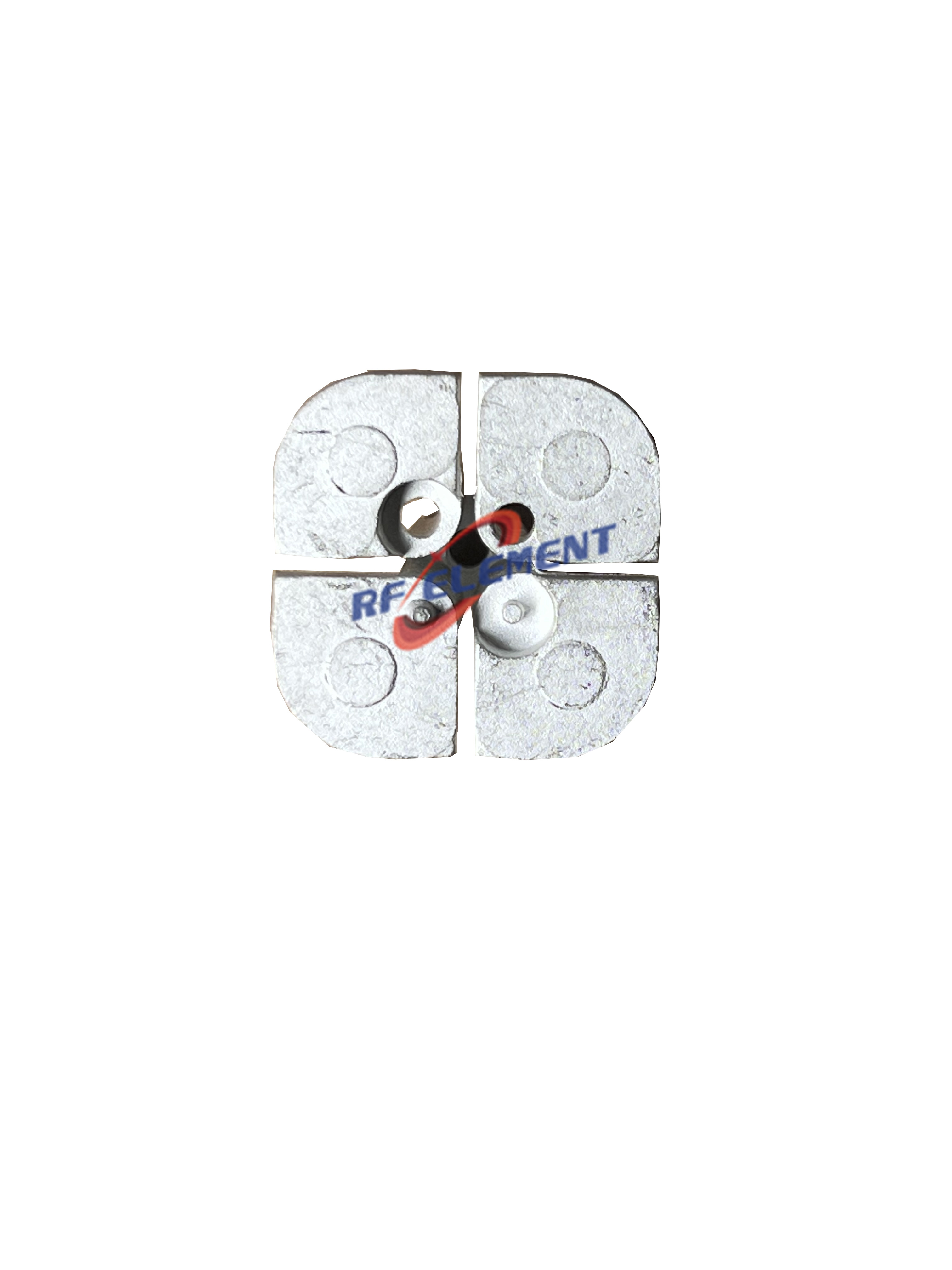
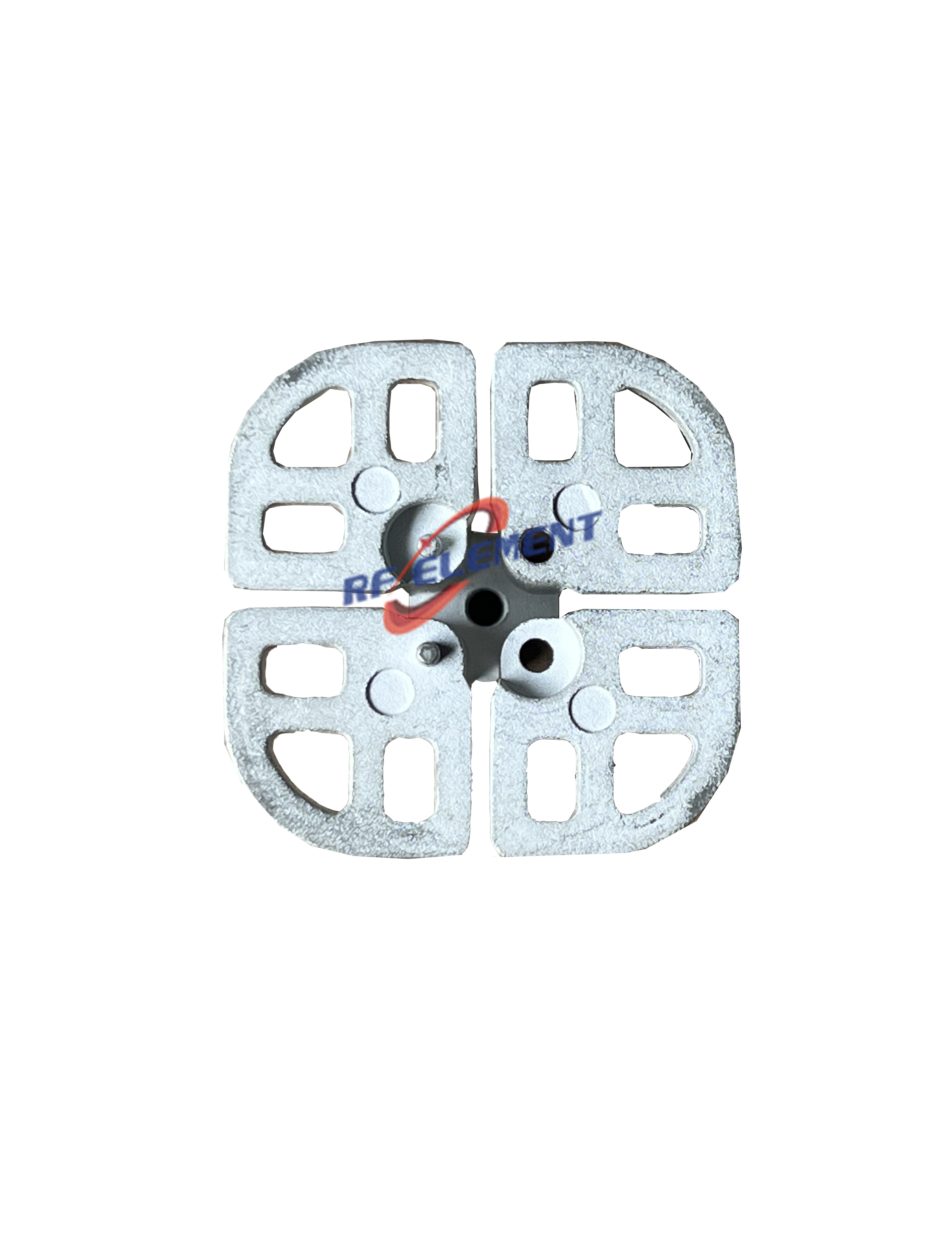
A housing cut from solid billet is the right answer for one proof of concept and the wrong answer for a product that will be built in the hundreds. Die casting puts the fins, the bosses and the gasket channel into the tool, so the wall thickness the thermal model asks for is the wall thickness every unit receives. We finish those parts with sandblasting followed by electroplating, two steps that matter for separate reasons: the first makes the surface regular enough for a gasket to seal the same way twice, and the second gives the conductive path that a shielded joint needs. A die-cast radiating element of ours comes off the same discipline at 33 by 33 by 23 mm and 7 grams, which is a small part to make a point with, except that the tolerance it holds is what keeps a 3300-3800 MHz array from shifting its match once it sits under a lid.
Multi-band front ends turn a cabinet into an antenna
A counter-UAV receiver rarely works on a single band. The multi-band radiator we build for these systems covers 433 MHz, 915 MHz, 1575 MHz, 2445 MHz and 5850 MHz on one vertical element at 2 to 8 dBi, holding VSWR below 2.0 across all five. Its larger relative, the full-band omni, extends the set with 868 MHz, 1.2 GHz, 1227.60 MHz and 1575.42 MHz and reaches 5 to 20 dBi, again under 2.0. Put parts like those inside a metal cabinet and the cabinet becomes a reflector nobody drew: the aperture has to be planned on the same sheet as the mounting plate, or the pattern measured in the chamber will not be the pattern measured on the mast. That is the practical reason our enclosure work starts from the antenna schedule rather than from the mechanical outline.
Seams, gaskets and the quiet path
Shielding is a question of joints before it is a question of materials. What leaks from a housing is rarely the alloy and almost always the seams: a lid carried on two fasteners, a connector flange bolted through paint, a vent cut longer than the shortest wavelength inside the box divided by twenty. We work backwards from the shortest wavelength of interest, spacing fasteners so no unbroken slot exceeds that figure, masking every mating face before coating, and using conductive gaskets at the interfaces that carry current. None of that is expensive on its own; what costs money is discovering it after the tool has been cut.
Weather is a mechanical test before it is an electrical one
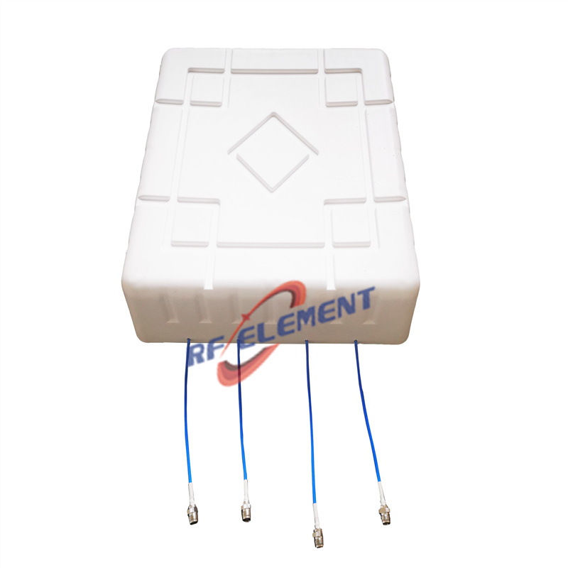
The outdoor year is the specification most projects under-document. Rain arrives sideways, the temperature swings through the full quoted range twice a day in some climates, and an antenna trimmed on the bench loses its match when water bridges the gap between radiator and housing. Continuity between lid and body, a drain path at the lowest point, and stainless hardware at every interface do more for field life than any additional decibel. The same logic explains why a fibreglass radome is often the cheapest way to protect an aperture: the shell passes the radio energy and takes the weather, so the metal behind it does not have to be sealed to the same standard.
The enclosure we already ship on a bridge radio
The clearest example of the whole approach in production is a 5 GHz bridge panel. It puts 18 dBi into the 5150-5850 MHz window in a 30 by 20 degree pattern, holds VSWR at or under 1.5, feeds through a single SMA port, and separates into two pieces on the drawing: a 305 by 305 by 25 mm radiator at 2.0 kg and a die-cast aluminium housing of 220 by 220 by 60 mm at 1.5 kg. The radiator is not hidden inside the housing; the housing is a structural shell that carries the mount, and the mechanical interface between the two was fixed before either part was tooled. Projects that come to us for a counter-UAV cabinet are usually asking for the same relationship on a larger scale.
What the low-PIM habit contributes to a cabinet
Enclosure design and intermodulation meet at the joint. A 4x4 MIMO small-cell panel of ours is rated at -153 dBc measured with two 20 W tones injected, across 617-4200 MHz, on four 4.3-10 female ports, in a housing of 450 by 450 by 110 mm at 2.5 kg. That number is not a property of the plastic cover; it is produced by the plating, the contact pressure and the flatness of the surfaces underneath. The same three variables set how quiet a high-power cabinet stays when several transmitters share it, which is why the assembly floor that builds our indoor parts also builds the shielded housings.
What leaves the shop with every housing
A first-article dimensional report from the coordinate measuring machine, a thermal image of the populated unit running at rated power, a continuity check across every gasket line, and an ingress test at the rating we quoted. The interface discipline that produces those reports is the same one our indoor MIMO ceiling plate gets, where two N-type female connections sit on a 215 by 215 mm plate weighing 0.8 kg, keeping 15 dB or more between the two paths. Verification is where a custom housing earns its cost back: a unit that reaches the field unmeasured returns as a field failure, and the freight alone on a return from a remote site usually exceeds the cost of the inspection that would have caught it.
What is not a good candidate for custom
Custom tooling is a real cost, and four situations will not pay it back. A programme with annual volumes in the tens and a single band is better served by a standard die-cast box with a custom front panel. A stage below roughly 10 W does not produce enough heat to justify a bespoke thermal path, and a commercial chassis will carry it. A project where the housing only protects equipment that is already separately sealed is buying a second enclosure it does not need. And a programme that has yet to fix its ingress rating and temperature-rise target is not ready to cut a tool at all, because the acceptance test defines the walls and not the other way round.
What we need to quote one
Send the band plan together with the per-stage power, the ambient range the site sees, the mounting interface, the ingress requirement and the annual quantity. We answer with a drawing concept, a material and finish recommendation, and a costed path from prototype to volume. A high-power housing is quoted from those six facts, and none of them substitutes for another. Write to sales@rfelement.com; a first reply will say whether a casting, a fabrication or a standard box is the honest answer.
TAG:Custom High-Power Counter-UAV Enclosure https://www.rfelement.com