The 5GHz WiFi Wireless Bridge Antenna Solution
A 5GHz WiFi wireless bridge replaces a leased line or a cable trench with a radio path between fixed points — two buildings across a yard, a CCTV cluster back to a control room, a production annex on the far side of a plant. The band is 5150-5850 MHz, and the arithmetic is unforgiving: every dB of antenna gain at each end either stretches the usable path, shrinks the hardware on the pole, or buys margin against interference from everything else sharing the unlicensed band. Our bridge panels are built around that arithmetic, and the choice between them is the choice between gain, beamwidth, and how much alignment discipline your crew can hold on installation day.
Gain and beamwidth move together
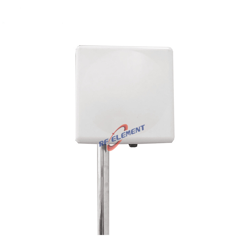
Our 5GHz wireless bridge panel antenna delivers 18 dBi over the 5150-5850 MHz band with a 30° horizontal by 20° vertical beam, a 305 × 305 × 25 mm panel weighing 2.0 kg, VSWR capped at 1.5, a 50 W power rating, and a single SMA port. The 30° beam is deliberately forgiving: a crew on a ladder can peak the link by hand and the misalignment tolerance absorbs the last few degrees of pole lean.
Two dB higher on the same footprint sits the 5GHz flat panel for WiFi bridging: 20 dBi, with the beam narrowed to 13° by 14°, VSWR no worse than 1.5, a single N-type port, and the same 305 × 305 × 25 mm, 2.0 kg platform. Those two extra dB at each end double the link margin or the distance — but they halve the aiming tolerance, so the mount has to hold aim within a degree or two instead of five. That trade, gain against beamwidth on one shared chassis, is the first decision in every bridge design we quote.
What the path survey decides before hardware
We ask for three facts before naming a model. The first is path length and obstruction: a clean rooftop-to-rooftop hop and a hop threading between warehouse walls need different beam discipline. The second is the mounting structure: a rigid steel pole holds a 13° beam, a timber mast or a wall bracket on a wind-loaded wall does not. The third is the radio: port count and polarization decide which of our panels pairs with it cleanly. None of this needs simulation to start — it needs the site sketch you already have.
What the sketch then buys you is margin, and margin is the currency of an unlicensed band. A link that closes with a handful of dB to spare on the day of installation will meet rain, new neighbours on adjacent channels, and a crane parked across the Fresnel zone within its first year; the same link planned with the gain step-up of the 20 dBi panel, or with the shorter path that a well-placed relay building allows, absorbs all three without a service call. This is also why we ask for the neighbourhood, not just the endpoints: an industrial estate at 5.8 GHz is a shared resource, and the antenna with the wider beam both hears and is heard by more of it.
Channels, DFS and the neighbours
The 5150-5850 MHz range is wide enough that most bridges never need to share a channel, but planning that separation is part of the antenna conversation. A wider beam hears more of the band's existing traffic during a site survey, which is genuinely useful when you are choosing a channel; the same width, once the link is live, collects more of everyone else's retries. Narrow-beam panels behave the other way round — harder to survey, quieter in service. We plan the pairing of beamwidth to channel plan with the customer rather than shipping a gain number and hoping the site cooperates.
The aluminum enclosure route
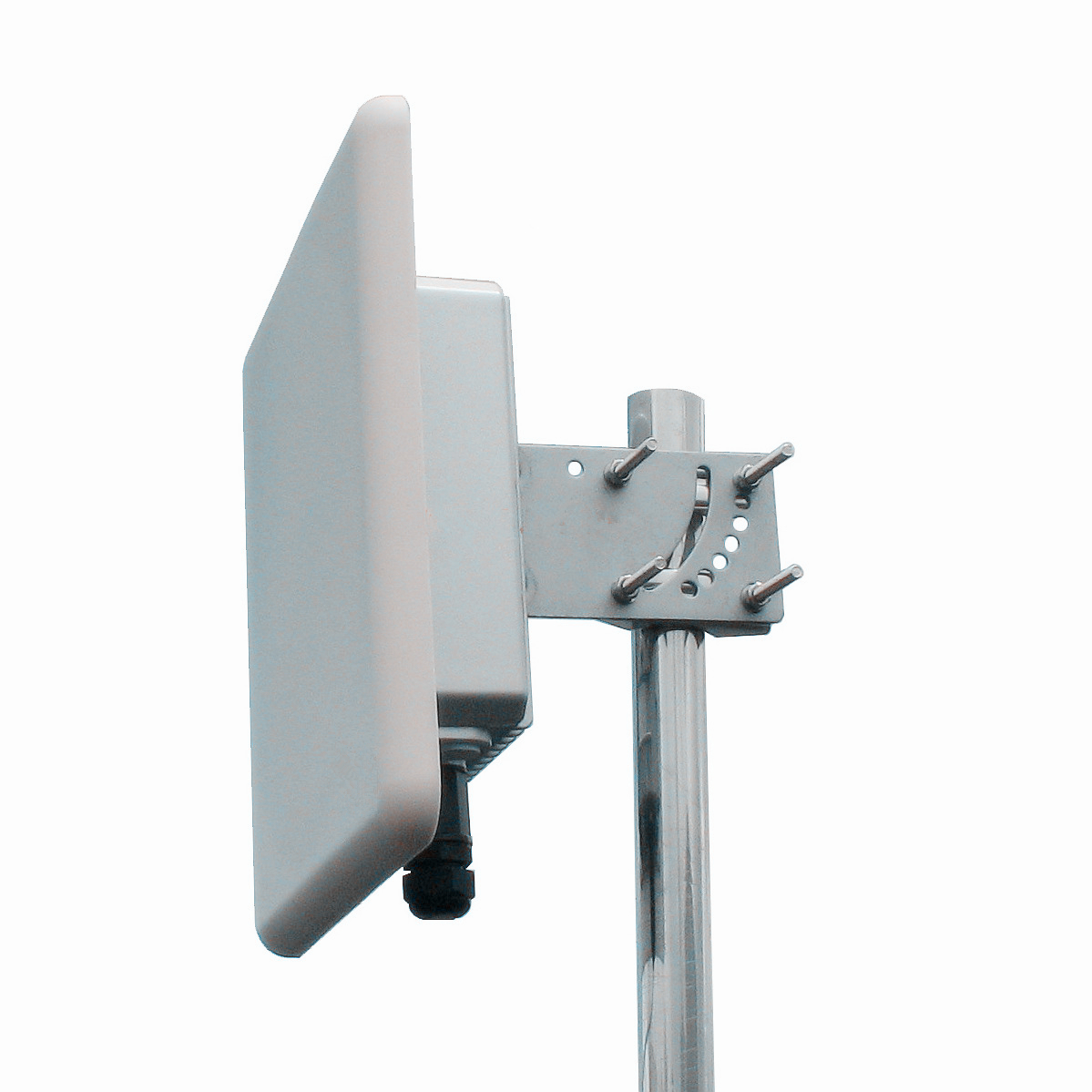
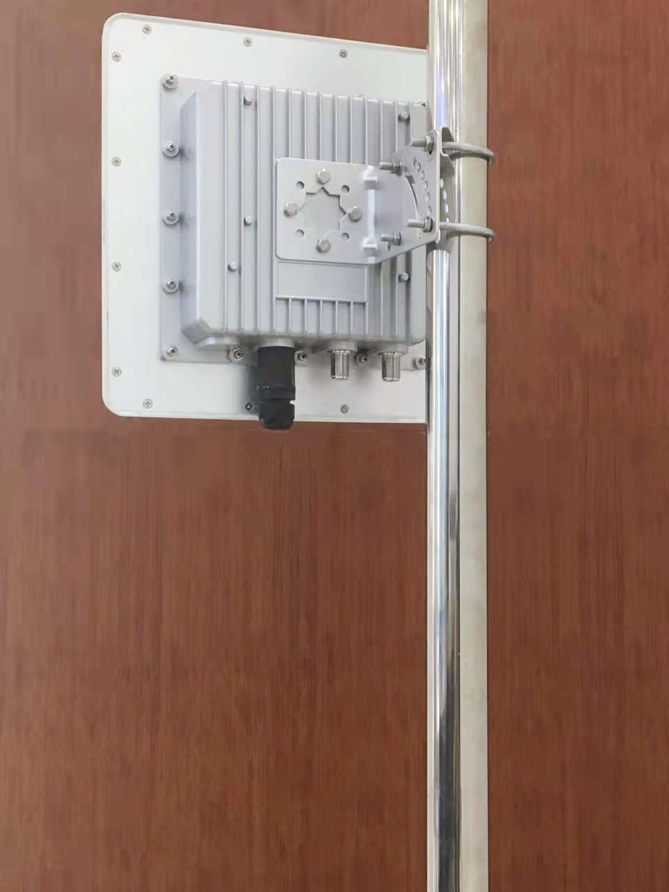
Some customers do not buy a radio at all — they design their own AP circuit board and need an antenna plus a housing around it. That is the path behind our 5GHz flat panel built for enhanced WiFi bridging, a case-engineered unit specified at 5150-5850 MHz, 18 dBi, VSWR below 1.8. Our bridge panel with aluminum enclosure pairs the 18 dBi antenna with a separate 220 × 220 × 60 mm aluminum housing weighing 1.5 kg, weatherproofed for the outdoor side while the customer's electronics live inside. Radome is ABS, the rated temperature span is -55° to +60° C, and mounting is pole-mount hardware. If your board outline changes, the enclosure changes with it — this is a production line we run, not a catalogue item we adapt.
Weight, weather and what the pole actually carries
The numbers worth carrying to the structural conversation are small and consistent. The 18 dBi panel is 2.0 kg on its own and 3.5 kg with the aluminum enclosure fitted; the 20 dBi panel is 2.0 kg; the radomes are ABS and the finishes are chosen so a white radome does not become a heat problem on a sun-facing wall. The rated operating span of -55° to +60° C covers unheated rooftops in continental winters and enclosed metal enclosures in summer sun, which are the two extremes bridge hardware actually meets. Against that, the wind load of a 305 × 305 mm flat plate is modest enough that most standard poles accept it without reinforcement — but we would rather the installer confirms the mount against the drawing than against habit.
Port count and the newer radios
Legacy bridge radios are single-port, and the single SMA port on the 18 dBi panel matches them without adapters. Newer hardware wants more paths: our dual-band WiFi panel for 4×4 radios carries four female N-type connectors on a 350 by 350 by 45 mm plate at 2.0 kg, with 16±1 dBi in the 2400-2500 MHz band and 18±1 dBi in the 5150-5850 MHz band — the part to quote when the bridge radio is 4×4 and the same pole must also serve 2.4 GHz coverage. Note that these bridge panels are vertically polarized, single polarization per port; two bridges sharing a rooftop therefore need angular or channel separation planned in, not discovered after the second crew arrives.
Where the wrong choice shows up
The 20 dBi, 13° panel is the wrong fit on anything that moves: a swaying mast, a bracket on a lightweight wall, a link that a maintenance crew re-aims without instruments — alignment drift on a 13° beam takes the link down before anyone notices why. Conversely, an 18 dBi panel held at 30° is the wrong fit when the link budget only closes with the extra margin of the narrower beam and there is no structural way to add it. And when the unlicensed 5 GHz band around the site is crowded past tolerable, the bridge conversation moves to our 13 GHz microwave directional antenna: 28-30 dBi at 12.7-13.4 GHz behind a beam barely 5 degrees wide and 3.5 degrees tall, a different regulatory and cost conversation, but one where the interference problem stops existing. For sites that need the panel to also carry access traffic rather than only the bridge backhaul, our low PIM 5G panel line covers 698-3800 MHz on the same family of mechanics.
From path survey to shipment
Send us the path survey — endpoints, heights, mount type — the port count on the radio, and, if you take the enclosure route, the AP board outline. Our reply names the model, attaches the complete spec table and the mounting drawing, and flags any polarization or separation issue we can see in your layout. Samples leave our production line within about five working days of a confirmed drawing, volume schedules are quoted once quantities are fixed, and MOQ gives a two-site pilot room without a container decision. Email it all to sales@rfelement.com — the figures in your survey are the figures the finished link delivers.
TAG:The 5GHz WiFi Wireless Bridge Antenna Solution https://www.rfelement.com