5GHz Panel Antenna | WiFi Flat Panel Antenna | 20dBi
Specifications
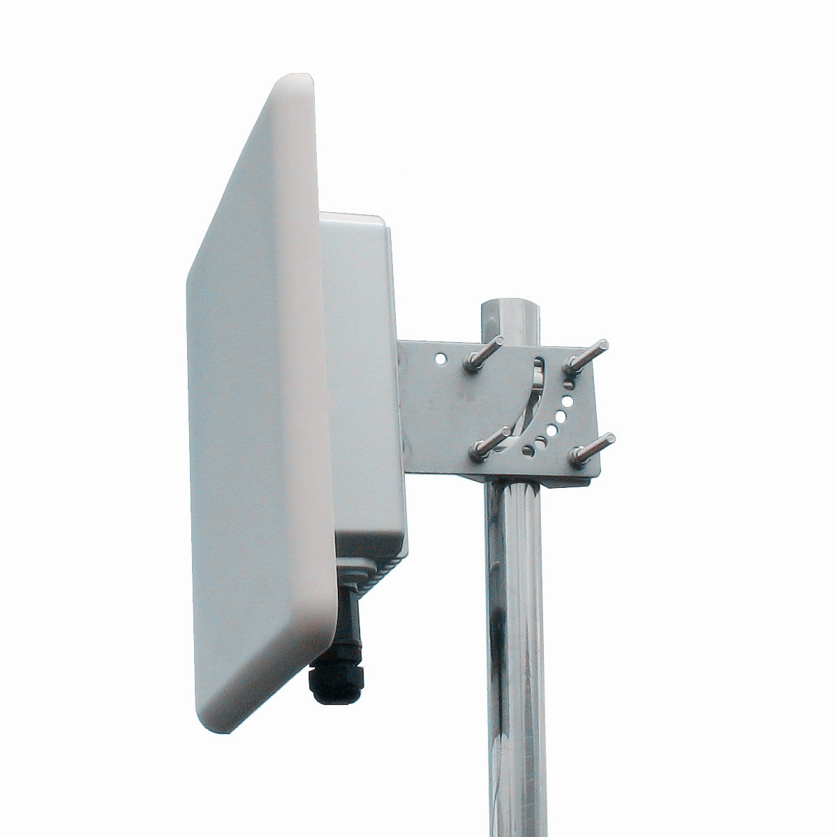
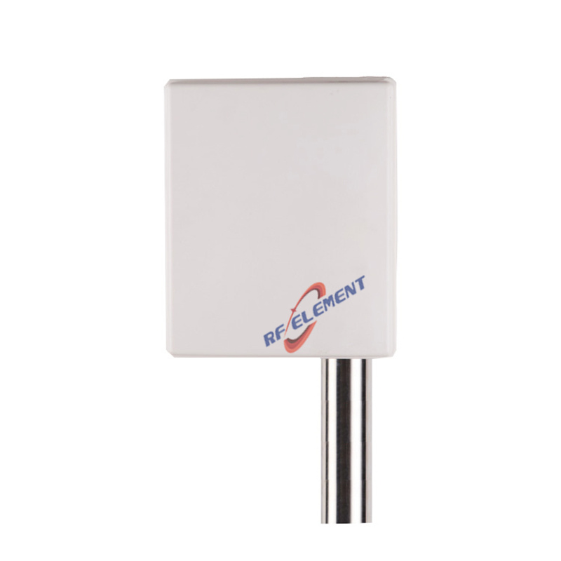
A 20 dBi flat panel for 5 GHz bridges and long range multipoint links, mounted on a 305 x 305 x 25 mm plate that weighs 2.0 kg. The horizontal beam is 13 degrees wide and the vertical beam 14 degrees, VSWR is at or below 1.5 across 5150-5850 MHz, and a single N-Type female port handles up to 50 W. It is intended for fixed outdoor links where both ends can be aligned precisely and the path has clear line of sight.
Twenty decibels at 5.8 GHz
Twenty decibels on both ends of a 5.8 GHz link adds 40 dB to the system budget compared with omni antennas at 10 dBi, which is enough to carry a 100 Mbps class link several kilometres with a clear path. The same gain is not achievable with a wider beam on a 305 mm plate, because the aperture sets the relationship between gain and beamwidth.
The practical limit on this antenna is not gain but the accuracy of the aim and the quality of the path. At 13 degrees, the beam covers about 23 m of width at 100 m and 228 m at 1 km. A one degree error at a kilometre moves the coverage edge by 17 m, which is why a link of this gain class is normally aligned with a signal meter rather than by eye.
Fresnel zone at 5.8 GHz
The first Fresnel zone radius at mid-path is about 5.1 m on a 1 km link at 5.8 GHz, smaller than at 2.4 GHz, which makes 5 GHz links easier to clear over the same terrain. The smaller zone is the main reason a 5 GHz link of the same length performs more consistently than a 2.4 GHz link, and it is why this antenna can be mounted lower on the same mast than a 2.4 GHz equivalent.
Ground reflection is the other factor. On a flat path with both antennas at similar heights, the reflected wave arrives within the beam and can cancel part of the direct signal. A small height difference between the two ends, or a slight downtilt, usually resolves it. The 14 degree vertical beam gives enough room to apply that tilt without losing the link.
| Frequency Range | 5150-5850MHz | |
| Polarization | Vertical | |
| Gain(dBi) | 20 | |
| Horizontal Beamwidth | 13° | |
| Vertical Beamwidth | 14° | |
| Impedance | 50Ω | |
| VSWR | ≤ 1.5 | |
| Maximum Power | 50W | |
| Connector Type | 1Port, N-Type Female | |
| Antenna Dimension(mm) | 305*305*25 | |
| Net Weight | 2.0 kg | |
| Operating Temperature | -55° to +60° C (-67° to +140° F) | |
| Radome Material | ABS | |
| Radome Color | White | |
| Mounting Options | Pole mounting | |
A 305 mm plate at 5.8 GHz
The same 305 mm plate that produces 18 dBi at 2.4 GHz produces 20 dBi at 5.8 GHz, because the aperture is a larger number of wavelengths at the higher band. That is also why the beam narrows from 22 to 13 degrees. The plate is thin at 25 mm, so it sits close to a mast or a wall and presents a modest wind profile despite the square face.
For a rooftop bridge, the flat form factor is easier to mount on a parapet than a dish and does not require the same rigidity in the mounting. For a link beyond about 8 km, a dish with 28 to 30 dBi is the correct tool and this panel is not a substitute.
Match and standard
VSWR of 1.5 or better across 5150-5850 MHz corresponds to a return loss above 14 dB, which is a comfortable match for any 802.11a, n or ac radio and for 802.11ax equipment on the same channels. The antenna is a passive component, so the standard named in the datasheet describes the radios it is normally paired with rather than a limitation.
The single port means one radio chain. For a 2x2 bridge, two of these panels are used with vertical and horizontal mounting respectively, which also provides polarisation diversity and roughly 3 dB of additional fade margin on a obstructed path.
Mounting
Fix the plate to a pole with the bracket supplied and keep at least 200 mm clearance from the pole surface. At 5.8 GHz a metal mast inside the near field produces a deeper null than at 2.4 GHz, and the effect appears as an unexplained 3 to 6 dB drop in received level.
Seal the connector and provide a drip loop. On a bridge link, the connector is exposed to wind-driven rain for years, and a single ingress point will degrade the link gradually rather than failing outright.
Ordering
N-Type female is standard, with radome colour and packing quantity confirmed at order. Samples in 3-5 days, production in 15-25 days.
Where the link needs a weatherproof metal housing rather than an ABS radome, the 18 dBi 5 GHz bridge panel antenna is supplied in a die-cast aluminium enclosure with an SMA output. For a 90 degree sector rather than a point-to-point link, the 19 dBi 5 GHz sector antenna covers a wide azimuth with two polarisations.
Send the link distance, the antenna heights and the required throughput. On a 5.8 GHz bridge those three numbers decide whether 20 dBi is enough or whether the path needs a dish.
FAQ — 5GHz Panel Antenna
What is the 5GHz Panel Antenna used for?
What frequency band does the 5GHz Panel Antenna cover?
What are the key specifications of the 5GHz Panel Antenna?
Can RF element customize the 5GHz Panel Antenna for my application?
What is the MOQ and lead time for the 5GHz Panel Antenna?
How do I get a quotation for the 5GHz Panel Antenna?