

Multi-Band Circular Polarized Panel Array: Custom Directional Antenna Design
1, Radiator: 9 x 2x2 circular polarized subarrays
2, Frequency: several discrete bands, est. 1.5-6GHz
3, Gain: est. 10-12dBic per subarray
4, Polarization: RHCP / LHCP
Specifications
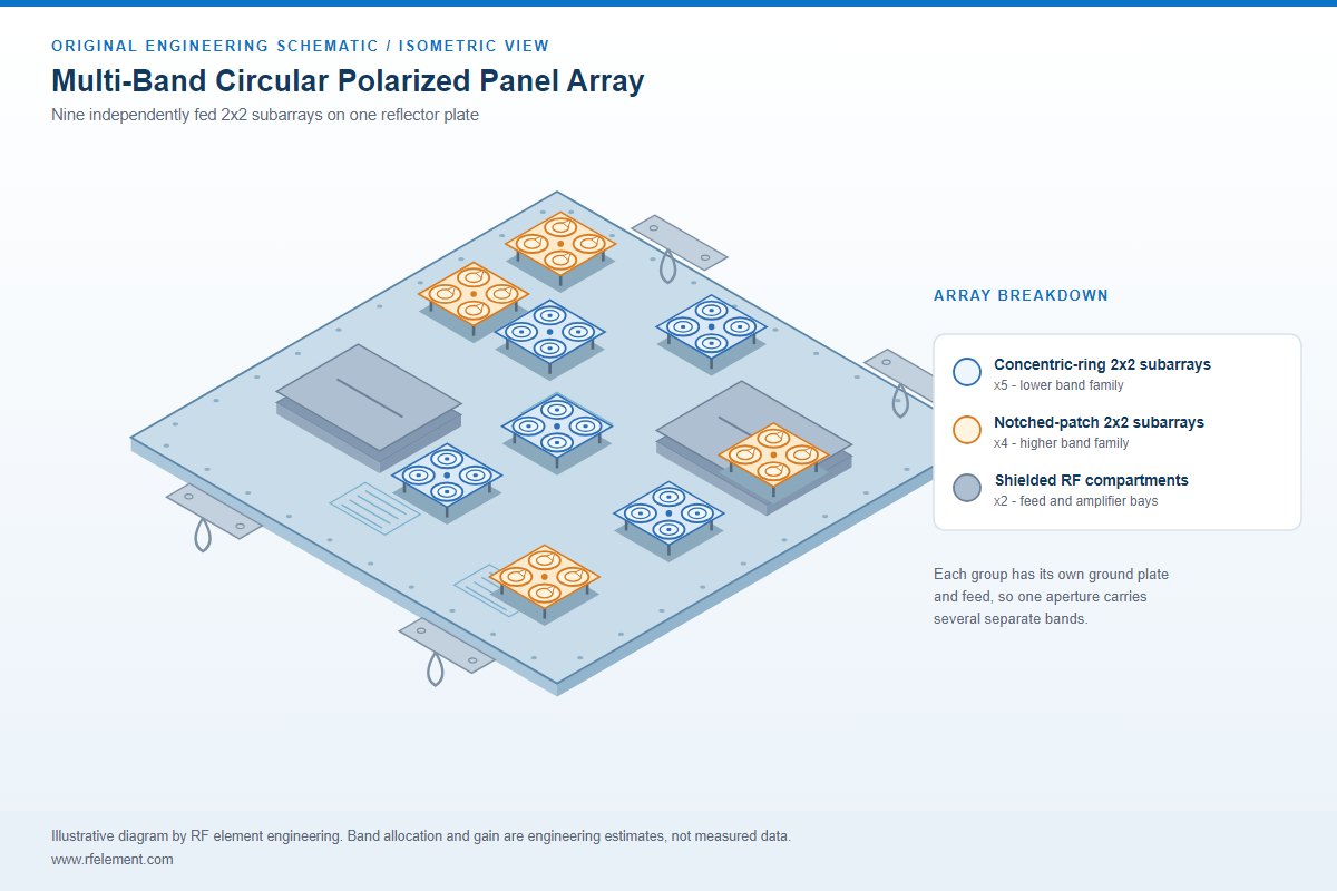
A multi-band circular polarized panel array is a directional antenna that carries independently fed 2x2 radiator groups on one shared reflector plate. Our engineers designed this array from the customer's requirement, and the 3D model shown here is our own design output: nine 2x2 subarrays split between two radiator families, two shielded RF compartments, three comb-shaped feed-network areas and four lifting-lug mounting ears, all carried on one square reflector plate so that several radios can share one aperture. The requirement fixed the bands, polarisation, gain target and mounting envelope, and our design questions were how to place several discrete bands on one aperture, how to keep the nine feeds isolated, and how to reach the gain target in every band. Every electrical figure below is a design target or a simulated value from that engineering stage; the finished antenna is verified on a VNA and in an anechoic chamber before release. Teams with a similar requirement can compare our custom antenna case studies or send their frequency plan and mechanical envelope to our engineers for the same design-to-production cycle.
What our engineers designed into the panel
The image is an enclosure-off view of the radiating layer as we laid it out, before the radome and final assembly. Two families of circular polarized radiators sit on the same reflector plate. Five groups use concentric-ring elements, each ring carried above a small square ground plate on four standoffs. Four groups use notched circular patches, arranged as a 2x2 cluster with each patch rotated by 90 degrees around a central cross feed, which is the standard sequential-rotation layout we used to widen the axial-ratio bandwidth. Because every 2x2 group has its own ground plate, its own standoffs and its own feed point, these are nine independent antennas sharing one mechanical aperture rather than one large phased array.
We allocated two shielded RF bays with slotted lids for the feed networks, filtering or amplification, and laid the comb-shaped microstrip traces beside them as distributed matching and power-division structures. Four lifting lugs with U-shaped eyes extend past the panel corners for a suspended installation, and small mounting holes run around the perimeter. The red, green and blue triad near the middle is the CAD origin marker, not a component. Our antenna radiating elements guide explains how these radiator forms behave once they are put above a reflector.
Why we chose a directional multi-band panel
Three decisions define the architecture. First, we placed every radiator above a flat reflector so each group radiates into a single hemisphere with a shaped beam; there is no cylindrical or colinear structure that would produce an omnidirectional pattern. Second, we used 90-degree sequential rotation on the four patches and concentric rings on the other groups to obtain circular polarization, which is the right choice when the polarization of the far end is unknown or rotating. Third, we sized the two radiator families differently on purpose: the larger rings serve the lower bands and the smaller notched patches serve the higher bands.
This is also why the plate is not a conventional base-station MIMO panel. A MIMO panel repeats identical dual-polarized radiators for the same band. Here we changed the element geometry from group to group to fit a frequency plan of several discrete bands into one housing. A comparable approach, built with a different radiator set and an octagonal reflector, is documented in our multi-band anti-drone antenna case. A 5G antenna design brief would instead call for a continuous wideband match across one span.
Setting the operating bands from the requirement
We sized each radiator from the requested bands rather than guessing a frequency from the picture. For the fundamental TM11 mode, the resonant frequency in GHz is roughly 176 divided by the product of the patch diameter in millimetres and the square root of the effective dielectric constant. An air-suspended radiator of this type has an effective constant close to 1.2 to 1.5, so a 25mm patch resonates near 6GHz, a 35mm patch near 4.4GHz, a 50mm patch near 3GHz and a 70mm patch near 2.1GHz. Annular rings of the same outer diameter resonate somewhat lower than a solid disc, typically by 20 to 40 percent.
Starting from the required bands, we assigned the larger concentric rings to the lower-band groups and the smaller notched patches to the higher-band groups. The panel edge was set by the mounting envelope from the brief, and the standoff height, ground plate and sequential-rotation feed were then fixed for each family. The two families on this plate cover several discrete bands within the 1.5 to 6GHz design range; the exact frequency plan belongs to the project and is agreed with the customer before tooling. A plan of this class is often built around 1575MHz, 2445MHz, 3500MHz and 5850MHz, which suits multi-band detection, counter-UAS and multi-system terminals.
One constraint shaped the layout: bands below 1GHz do not fit this aperture. A 433MHz or 915MHz patch needs a radiator several times the diameter of these elements, and nine such groups would not fit inside the outline. Low-band coverage in a multi-band system is normally handled by a separate helix, dipole or blade antenna. We fixed the final frequency plan with a full-wave model of one element from each family and confirmed it with an S11 sweep on the first prototype.
What our engineers designed into the panel
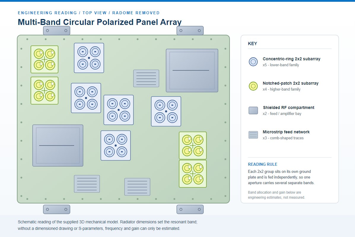
The image is an enclosure-off view of the radiating layer as we laid it out, before the radome and final assembly. Two families of circular polarized radiators sit on the same reflector plate. Five groups use concentric-ring elements, each ring carried above a small square ground plate on four standoffs. Four groups use notched circular patches, arranged as a 2x2 cluster with each patch rotated by 90 degrees around a central cross feed, which is the standard sequential-rotation layout we used to widen the axial-ratio bandwidth. Because every 2x2 group has its own ground plate, its own standoffs and its own feed point, these are nine independent antennas sharing one mechanical aperture rather than one large phased array.
We allocated two shielded RF bays with slotted lids for the feed networks, filtering or amplification, and laid the comb-shaped microstrip traces beside them as distributed matching and power-division structures. Four lifting lugs with U-shaped eyes extend past the panel corners for a suspended installation, and small mounting holes run around the perimeter. The red, green and blue triad near the middle is the CAD origin marker, not a component. Our antenna radiating elements guide explains how these radiator forms behave once they are put above a reflector.
Why we chose a directional multi-band panel
Three decisions define the architecture. First, we placed every radiator above a flat reflector so each group radiates into a single hemisphere with a shaped beam; there is no cylindrical or colinear structure that would produce an omnidirectional pattern. Second, we used 90-degree sequential rotation on the four patches and concentric rings on the other groups to obtain circular polarization, which is the right choice when the polarization of the far end is unknown or rotating. Third, we sized the two radiator families differently on purpose: the larger rings serve the lower bands and the smaller notched patches serve the higher bands.
This is also why the plate is not a conventional base-station MIMO panel. A MIMO panel repeats identical dual-polarized radiators for the same band. Here we changed the element geometry from group to group to fit a frequency plan of several discrete bands into one housing. A comparable approach, built with a different radiator set and an octagonal reflector, is documented in our multi-band anti-drone antenna case. A 5G antenna design brief would instead call for a continuous wideband match across one span.
Setting the operating bands from the requirement
We sized each radiator from the requested bands rather than guessing a frequency from the picture. For the fundamental TM11 mode, the resonant frequency in GHz is roughly 176 divided by the product of the patch diameter in millimetres and the square root of the effective dielectric constant. An air-suspended radiator of this type has an effective constant close to 1.2 to 1.5, so a 25mm patch resonates near 6GHz, a 35mm patch near 4.4GHz, a 50mm patch near 3GHz and a 70mm patch near 2.1GHz. Annular rings of the same outer diameter resonate somewhat lower than a solid disc, typically by 20 to 40 percent.
Starting from the required bands, we assigned the larger concentric rings to the lower-band groups and the smaller notched patches to the higher-band groups. The panel edge was set by the mounting envelope from the brief, and the standoff height, ground plate and sequential-rotation feed were then fixed for each family. The two families on this plate cover several discrete bands within the 1.5 to 6GHz design range; the exact frequency plan belongs to the project and is agreed with the customer before tooling. A plan of this class is often built around 1575MHz, 2445MHz, 3500MHz and 5850MHz, which suits multi-band detection, counter-UAS and multi-system terminals.
One constraint shaped the layout: bands below 1GHz do not fit this aperture. A 433MHz or 915MHz patch needs a radiator several times the diameter of these elements, and nine such groups would not fit inside the outline. Low-band coverage in a multi-band system is normally handled by a separate helix, dipole or blade antenna. We fixed the final frequency plan with a full-wave model of one element from each family and confirmed it with an S11 sweep on the first prototype.
FAQ — Multi-Band Circular Polarized Panel Array: Custom Directional Antenna Design
What is the Multi-Band Circular Polarized Panel Array: Custom Directional Antenna Design used for?
What frequency band does the Multi-Band Circular Polarized Panel Array: Custom Directional Antenna Design cover?
What are the key specifications of the Multi-Band Circular Polarized Panel Array: Custom Directional Antenna Design?
Can RF element customize the Multi-Band Circular Polarized Panel Array: Custom Directional Antenna Design for my application?
What is the MOQ and lead time for the Multi-Band Circular Polarized Panel Array: Custom Directional Antenna Design?
How do I get a quotation for the Multi-Band Circular Polarized Panel Array: Custom Directional Antenna Design?


