There is no such thing as a generic 4G LTE antenna. What a site actually buys is a family of parts that work the same cellular bands and differ in nearly everything else — radiation pattern, polarization, port count, housing, and the position on a site that each part is allowed to occupy. We manufacture that family, and every part in the line works the 698-2700 MHz band as one continuous range, with several reaching 4200 MHz for sites that already carry mid-band 5G. The order below is the order we actually use when a customer sends a site sketch, and it is close to the reverse of the order in which most of the mistakes we are shown were made.
The band comes first, and it decides everything downstream
Every part we quote handles 698-2700 MHz without a break, and 698-960 MHz forms the low sub-range that carries the coverage layer in most deployments. That continuity matters more than it sounds: a site that spans rural 800 MHz and urban 2600 MHz can be built from one antenna family instead of two, and one spare part serves both. Where a project already carries mid-band 5G, the same mechanics are available up to 4200 MHz, which is why several of the parts below are specified wider than a pure LTE job would require. Choosing the band before the pattern is not bureaucracy — it removes half the catalogue before the interesting questions start.
Polarization is a decision about the radio, not the antenna
Vertical polarization is the default in cellular because the handsets and vehicle terminals it serves are vertically oriented. Our omni and single-element ceiling parts are vertically polarized for exactly that reason. The moment the radio wants two data streams, polarization becomes the mechanism: a ±45° cross-polarized pair carries two independent paths on one housing, and the isolation between those paths is what keeps the streams separable at the receiver. We publish that isolation figure rather than implying it — the 2x2 panel in the line carries a published value of 20 dB or more, which is the number that makes a 2x2 claim honest.
Gain and beamwidth are one decision wearing two labels
Gain is not free. Every dB added to a panel comes out of the pattern: the beam narrows, and the aiming tolerance narrows with it. A 12 dBi sector at 90 degrees horizontal is forgiving to install and covers a wide urban slice; a 14 dBi dual-band panel at 15 degrees vertical concentrates the same power into a strip. What we tell customers is to decide how much aiming precision the mount can actually hold — a rigid steel pole and a lightweight wall bracket are not the same engineering problem — and then take the gain the structure can keep aimed. An antenna that performs to specification only while perfectly aligned is a maintenance liability dressed as a specification advantage.
Indoor and outdoor are different parts, not the same part with a bracket
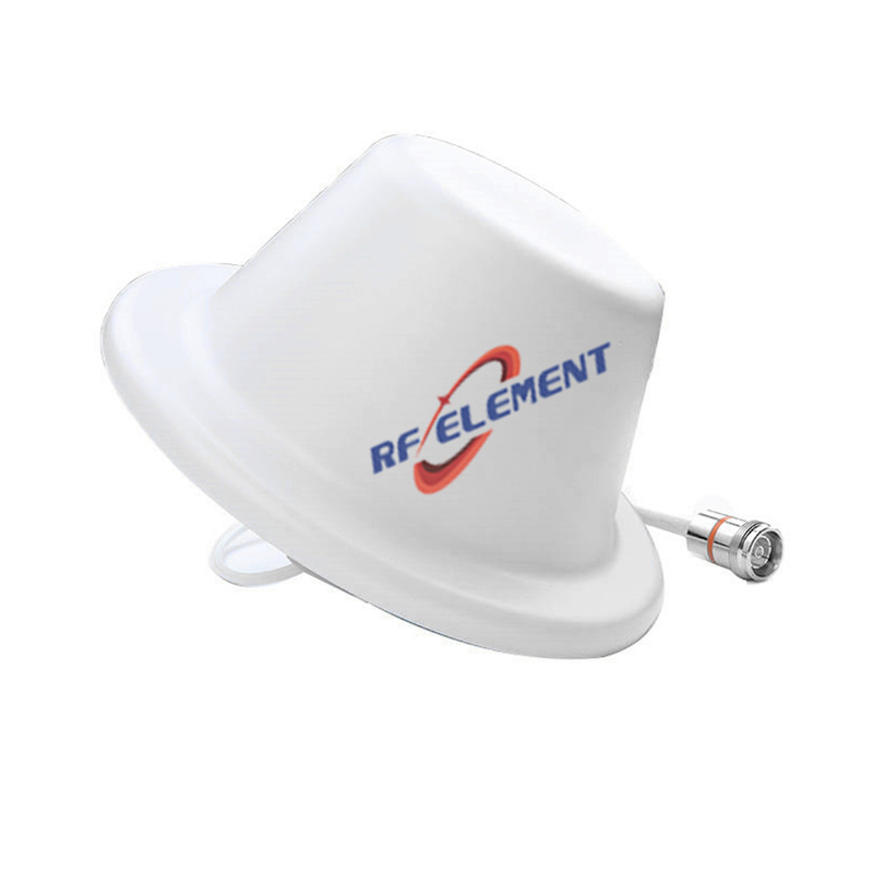
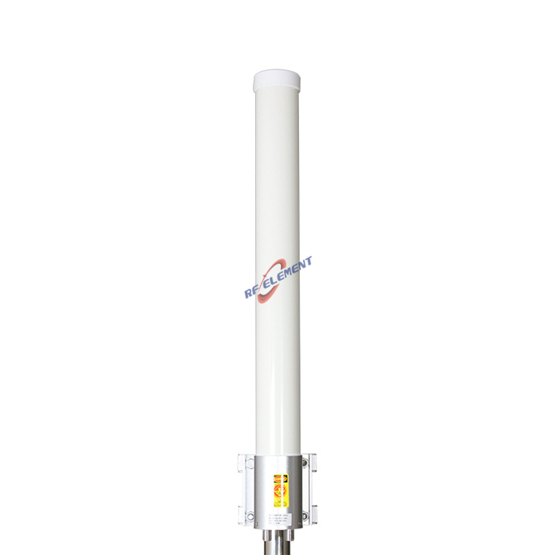
Indoors, the 4G LTE ceiling disc does the last-metre work: 698-2700 MHz on vertical polarization, 3 dBi into a 360° horizontal and 60° vertical pattern, VSWR held under 1.5, rated to 50 W, one N-type female input, and a white ABS body measuring 185 mm across by 90 mm deep, 0.4 kg, with wall and ceiling fasteners already in the box. Its operating window of -55 °C through +60 °C, and the 3 dBi gain level itself, are deliberate: an indoor disc is there to distribute a signal that is already present, not to reach a tower. Outdoors, the MIMO omni for 698-2700 MHz puts the same band on a pole-mounted tube 700 mm long and 75 mm across, 2.0 kg, 4 dBi spread across a 360° horizontal and 60° vertical pattern, VSWR within 2.0, and 100 W of handling through two N-type female inputs. Two streams on one omni at 4 dBi is the honest way to serve a site whose approach direction cannot be predicted.
The sector family, and when a sector beats an omni
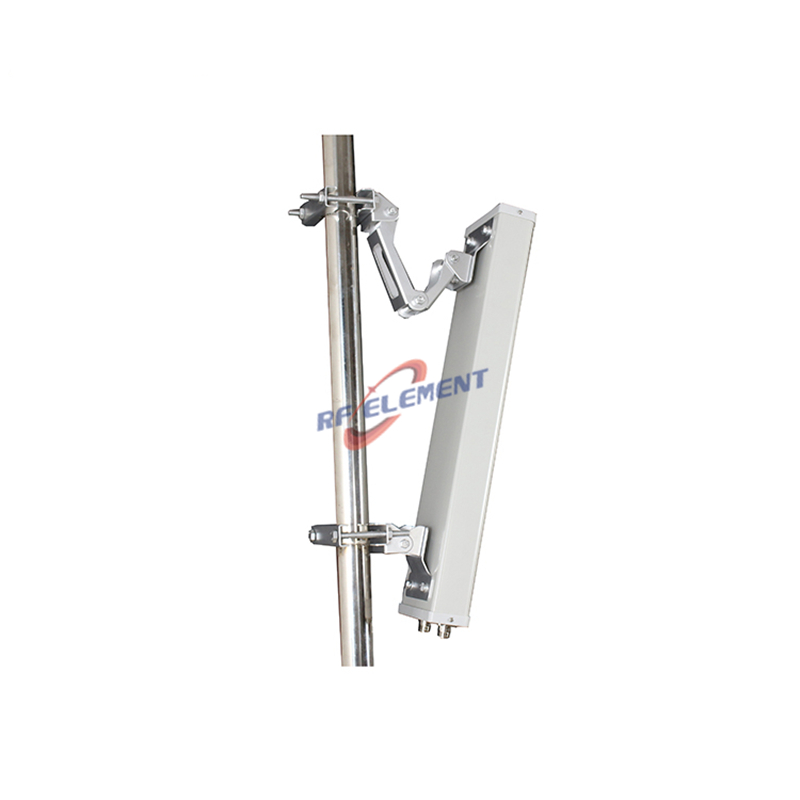
Where coverage is directional, the geometry changes everything: a sector plate cut at 90 degrees puts 12 dBi into a 90-degree horizontal slice of the 698-2700 MHz band from a PVC housing of 5.5 kg. Where a site wants two streams per sector rather than one, the ±45° MIMO sector serves a narrower 65-degree arc at 7 dBi on a body of 2.5 kg. The trade is visible in one line: the MIMO part gives up 5 dB of gain to gain a second polarization, and that is a fair trade only when the radio can actually drive two paths.
Where the antenna line meets the radio line
A project that spans LTE and 5G does not need two antenna families. The 698-4200 MHz 2x2 panel spans the full range on ±45° polarization at 5±0.5 dBi, with an 80±10° horizontal and 50±10° vertical pattern, VSWR inside 1.8, third-order intermodulation no worse than -153 dBc when driven by 2×20 W carriers, front-to-back rejection of 10 dB or more, isolation of 20 dB or more, rated to 50 W, with two ports that accept either 4.3-10 or N-type female inputs, in a housing weighing 1.0 kg and measuring 310 by 230 by 73 mm. Passive intermodulation stops being a footnote on sites where several carriers share the metal, and for those the low-PIM panel line is specified at -153 dBc against 2×43 dBm tones over 698-3800 MHz.
Feeder loss is the gain nobody budgets for
A customer asks for 12 dBi and then installs a 10-metre run of thin coaxial cable that gives back 3 of them. The arithmetic is unforgiving: cable loss sits before the receiver and after the transmitter, and it cannot be recovered by choosing a bigger antenna. Two habits fix most of it. Keep the radio close to the antenna wherever the site allows, and specify the joint properly — a torqued, properly plated interface instead of a hand-tight adapter stack. On outdoor mounts the second habit extends to weatherproofing every joint, because a corroded interface is both a loss and a passive intermodulation source, and the second problem is the one that survives every subsequent troubleshooting round.
Where the wrong choice shows up
The ceiling disc bolted onto an outdoor wall is the classic one: 3 dBi indoors is a distribution aid, and outdoors it becomes a 360° radiator that hears the whole neighbourhood and delivers nothing useful to a tower 900 metres away. The omni on a rooftop where all traffic arrives from one quadrant is the second: a 360° pattern spends three quarters of its radiated power where nobody is listening, which lifts the noise floor of every receiver on the roof. The third is the reverse of the first — a 90-degree sector aimed indoors, where 12 dBi and an 18° vertical beam land on one floor of one building and leave the rest of the site dark. Each of these is a decision made before any hardware was ordered.
When the asset itself reports
Not every 4G LTE antenna serves people. Trackers, telemetry boxes and vehicle units mount the radio on the thing being tracked, and the 4G/5G GPS puck exists for that shape of job: a cellular span of 700-3800 MHz at 3 dBi or better, a GNSS channel at 1575.42 MHz plus or minus 5 MHz, two SMA male connectors, a black ABS body measuring 80 mm across by 27 mm high, 0.2 kg, and a rating of -40 °C through +60 °C for the mounting points that see the worst of the weather. One puck delivers both the cellular link and the position fix, which is normally the entire antenna bill for a tracker.
What we need to name a part
Send the band plan, the height and structure of the mount, whether the radio is single-path or dual-path, and how the site is shared between carriers. We come back with the part named, the specification sheet plus the mounting drawing attached, and a note on any coverage or intermodulation risk the layout shows. Samples ship about a week after the drawing is frozen, volume scheduling is quoted after quantities are agreed, and the order minimum is small enough for a pilot site to be instrumented without a container commitment. Write to sales@rfelement.com — the numbers in your site sketch are the numbers your installation will be measured against.
TAG:4G LTE Antenna: A Comprehensive Guide https://www.rfelement.com