Base station planning starts at the antenna, because the antenna decides the shape of the cell before the radio transmits a single watt. A rural site that must light up a valley along a highway behaves nothing like an urban rooftop split into three dense sectors, and the 4G LTE antenna you bolt to the steel is where that difference becomes physical. The decisions below follow the order a site engineer meets them: coverage geometry, gain per sub-band, tilt, port count, interference discipline, and the mechanical realities of tower work.
Omni or sector: the geometry decision
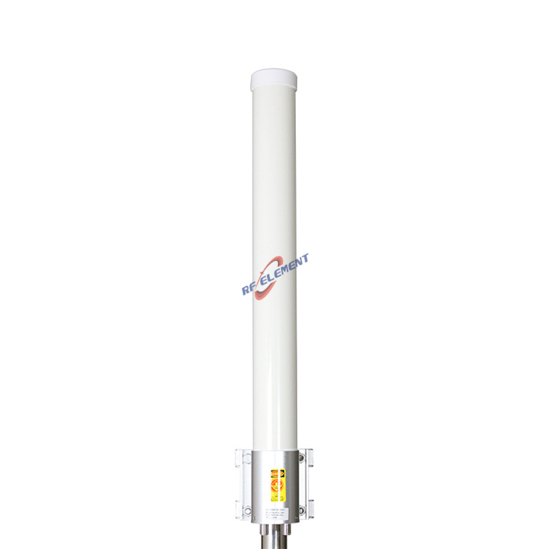
The first question is directional reach against all-around presence. A single omnidirectional radiator serves an isolated site — a village at the end of a road, a quarry, a farm cluster — where subscribers arrive from every bearing and traffic is light. Our fiberglass low PIM outdoor omni puts 4 dBi of vertical polarization onto a 360° pattern from a single 7/16 DIN interface, with a 75° vertical beam inside a 1200 mm fiberglass tube just 52 mm across, 2.5 kg on the clamp.
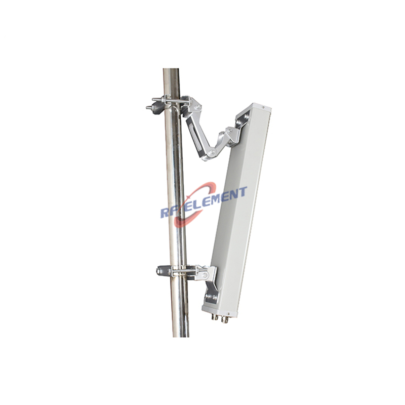
Once one direction carries more traffic than the others — a highway corridor, a town center, an industrial park — the site graduates to sectors. A three-sector arrangement at 90° or 65° per face aims gain where the users are and lets the back of the antenna stay quiet, which is where the front-to-back ratio earns its keep. The 90-degree LTE sector in our catalogue publishes 12 dBi at 698-960 MHz, stepping to 15 dBi higher in band, and holding a 90-degree horizontal beam within ±5° with front-to-back separation above 20 dB, so energy that would have spilled into the neighbouring cell is folded back into the serving sector.
Reading the sub-band gain rows correctly
Catalogue gain is never one number for an antenna that spans 698-2700 MHz, and the reason is physics rather than marketing. The 90° sector publishes 12 dBi in the 698-960 MHz sub-band, stepping up to 15 dBi once the carrier moves into 1710-2700 MHz. Low-band signals propagate farther and diffract around terrain better, so the antenna needs less gain to close a rural cell; high-band signals attenuate faster, and the extra 3 dB stretches the cell edge back out. Budget the link with the row that matches your carrier's band, not with the boldest figure on the page — a plan built on 15 dBi that only transmits at 700 MHz will fall short of its coverage map.
The vertical beam narrows as gain rises: 18° in the low sub-band and 9° in the high one for that same sector. That narrowing is what makes tilt a first-order decision rather than a fine adjustment.
Tilt and the near-tower gap
Every degree of downward tilt moves the cell edge closer and fattens the signal directly under the tower. Leave a 9° vertical beam untilted on a 40 m tower and the strongest energy sails over the heads of users at 300 m while the cell edge starves. With a beam that narrow, one degree of mechanical tilt is a measurable change of coverage, so the tilt plan belongs in the site design review, not in the climber's judgment on installation day. Omni patterns with a 75° vertical beam are far more forgiving of an imperfect tilt, which is one more reason they suit simple rural sites.
Ports: match the antenna to the radio
An LTE radio that runs 2T2R needs two antenna paths, and there are two ways to provide them. The traditional way hangs two single-polarization panels and aims each one by hand. The compact way is a cross-polarized unit: our ±45° MIMO sector carries both polarizations on one reflector in a 65±5° beam, and the whole assembly measures 450 × 280 × 180 mm at 2.5 kg — roughly half the frontal area of the 900 × 325 × 140 mm, 5.5 kg two-panel equivalent. For omni sites, the fiberglass MIMO omni brings two N-type ports to a 75 mm × 700 mm radome at 2.0 kg, and the 4-port LTE omni steps up to four connectors for 4×4 radios without adding a second antenna to the tower.
PIM discipline when the tower gets crowded
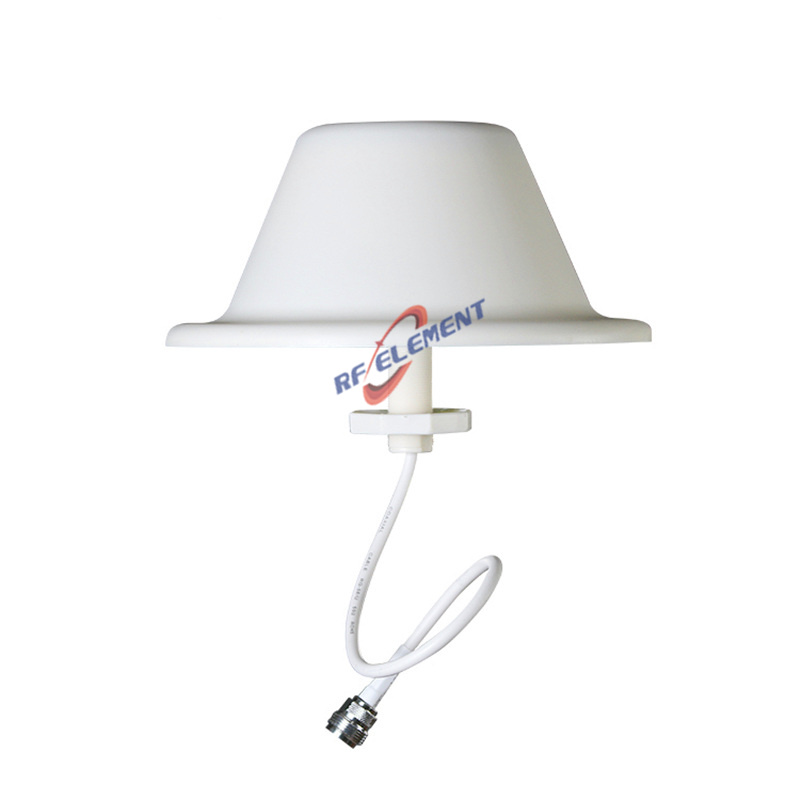
Rooftops and tower clusters concentrate transmitters, and every added carrier raises the passive-intermodulation risk: two strong signals mixing in a corroded joint land right in your own receive band. Where sites share steel with other operators, specify the low PIM omni — it holds third-order intermodulation below -150 dBc when the bench drives it with 2×20 W tones, and the single 7/16 DIN interface keeps the high-power path out of the small N-type connectors that suffer most from intermodulation. Our low PIM antenna line extends the same discipline across panel and ceiling formats for indoor base equipment.
Where the wrong choice shows up
An omni on a three-carrier urban rooftop puts 4 dBi into every direction including the ones the neighbour cell already owns; interference, not range, becomes the limiting factor, and the fix is a sector split. Conversely, a 15 dBi sector on a lonely farm site aims its quiet back side at half the subscribers and burns tower height to compensate. Hanging a 4-port antenna for a 2-port radio only caps two connectors and collects wind load for nothing, while a 2-port antenna on a 4×4 radio strands half the radio's capacity with no upgrade path short of a tower climb.
From order to tower
Tell us the band plan, the tower height, and the radio's port count, and we answer with the matched model, its specification table, and the mechanical drawing for the mount. Sample units leave our production floor within days of an approved drawing, volume batches follow a quoted factory calendar, and MOQ stays low enough that a pilot site never waits on container-scale commitments. Write to sales@rfelement.com and the numbers you plan with will be the numbers the tower delivers.
TAG:4G LTE Antenna Selection of Base Stations https://www.rfelement.com