LoRa Antenna Design Guide: Band, Type, Gain and Placement
A LoRa request usually arrives as a protocol and a target distance, and neither of them can be quoted. What can be quoted is a sub-band, a mounting position, a mechanical envelope and an environment. Getting those four answers onto one page is most of the work of specifying a LoRa antenna, and it is what this guide is organised around.
It deals with the antenna end of the link, meaning the part that sits on the mast, the wall or inside the housing. Everything on the module side, from the radio front end to the board layout, belongs to the module vendor and is deliberately left out.
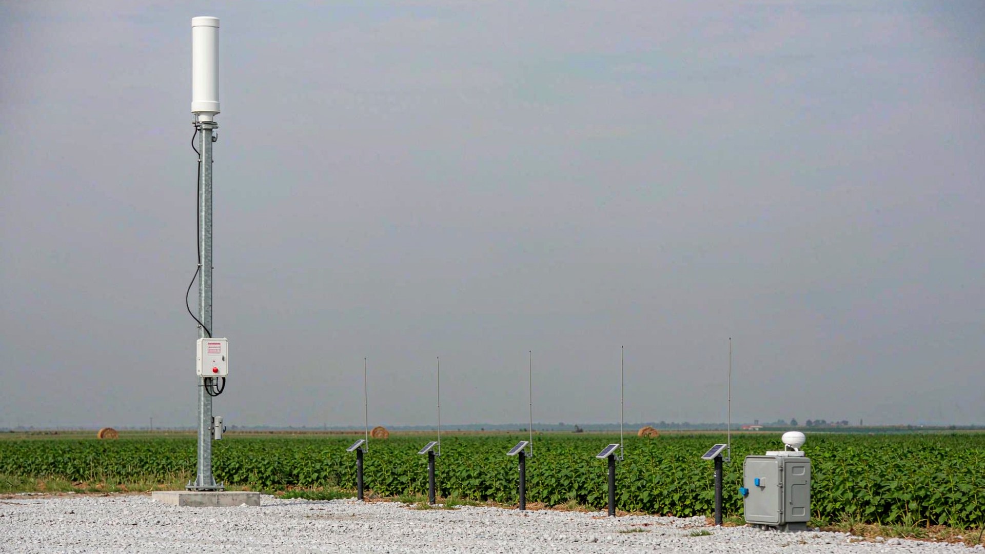
1. The four inputs
Sub-band, mounting position, envelope, environment. Each one removes options rather than adding them. The first settles which parts are usable at all, the second decides whether the pattern can be aimed, the third caps how much radiator will physically fit, and the fourth fixes the materials and the finish. A brief carrying all four can be quoted without a single question coming back. A brief carrying only the protocol is a guess wearing the clothes of a requirement.
2. Sub-band before anything else
LoRa is a modulation, and the same modulation is used on windows that sit tens of megahertz apart. Europe and India work around 860-870 MHz, North America around 902-928 MHz, and a long tail of legacy 824-960 MHz systems still runs underneath both. Sites outside those three windows can use the 428-438 MHz family. The sub-band belongs in the part name rather than in a note, because a radiator trimmed for one window will not hold its performance on another, and that difference is invisible until the hardware is up.
3. The shape of the site decides the family
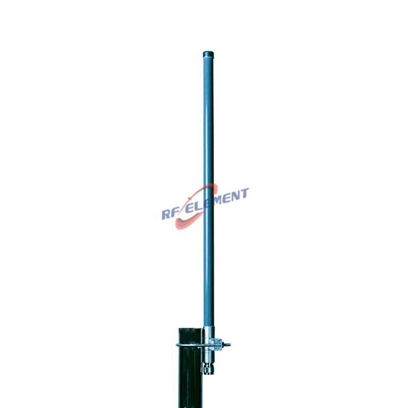
Where nodes surround the mast, or move around it, the antenna has to radiate in every direction and the answer is an omni. Our 5 dBi LoRa omni covers both main windows from a single unit, and the 8 dBi detachable LoRa omni does the same on a longer body for a mast that can carry it. Where cellular traffic shares the same pole, an 824-960 MHz omni covers the whole legacy window in one part.
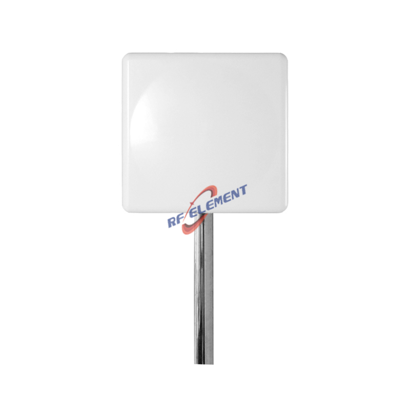
Where the traffic sits on one side of a tower, a sector does more with the same transmitter. The 900-930 MHz panel holds 11 dBi across a 55 by 50 degree sector, and it is the honest choice for a yard, a dock, or a single face of a building.
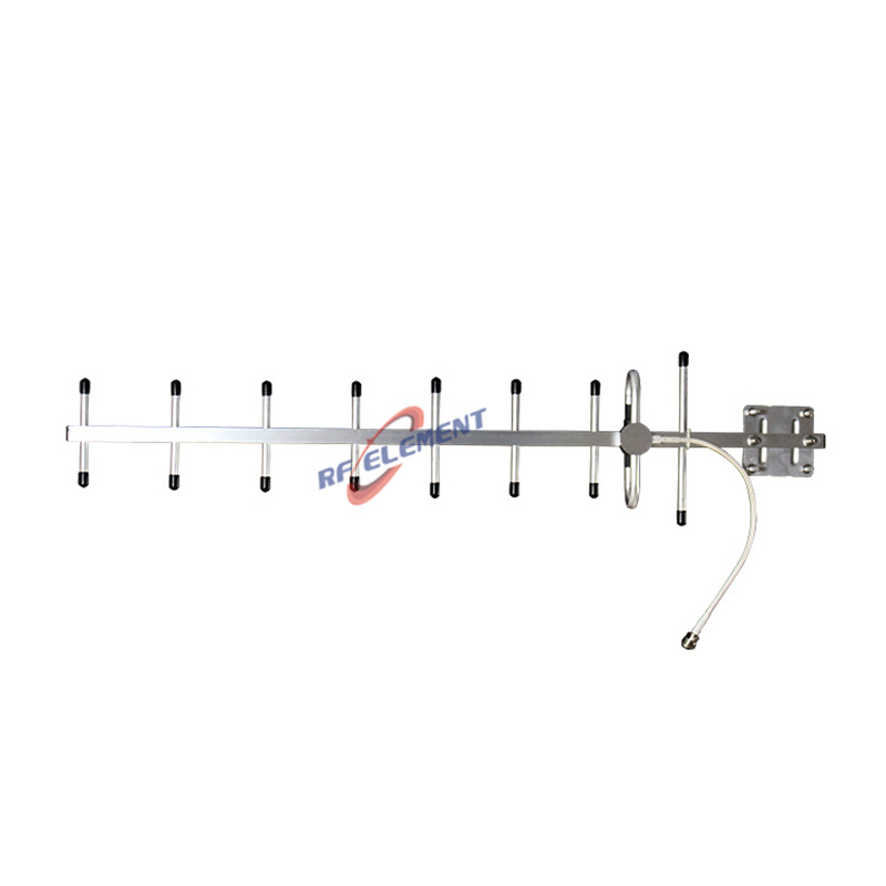
Where the far end is a fixed point that will never move, the antenna can be aimed at it. The 900 MHz yagi puts 14 dBi into a 40 by 35 degree beam on an aluminium boom. Aimed antennas on nodes that move or surround the mast are the mismatch we are shown most often, and it is the pattern that looks generous on paper that disappoints in service.
Sites outside all the main windows take the 433 MHz omni, which trades a considerably longer body for its band.
4. The envelope decides the available gain
The space an antenna can occupy sets how much radiator fits, and the radiator sets the gain. Our omni family runs from a 600 mm body 22 mm across at 1.0 kg for the 5 dBi part, through 1200 mm at 3.5 kg for the 8 dBi detachable version, to a 900-930 MHz 8 dBi omni that reaches 1540 mm at 1.5 kg. Maximum length, maximum diameter, weight at the bracket and the mount the structure will accept are worth measuring before a family is shortlisted, not after. Where the mast is already occupied, the clamp stops being an accessory: a longer body carries more sail area, and the mount has to hold its angle through a season of weather before the pattern can be relied on. The two-piece detachable construction exists so that the base can be fitted, sealed and cabled first, with the radiator added afterwards.
5. Gateways and nodes are specified separately
The two ends of a LoRaWAN link are not chosen from one brief. A gateway is judged on what it can hear, so it wants height and a wide omni pattern, and its mount usually has room for a long body. A node is judged on fitting inside a product and surviving its own installation, so it runs a lower gain figure, a shorter body, and a connector picked to suit the enclosure. In day to day work the node part is specified alongside the enclosure rather than on its own, because the connector, the cable exit and the sealing face are one mechanical problem, while the gateway part is specified alongside the mast and the site. The LoRa antenna range is built so that both ends can be quoted from the same place without one compromising the other.
6. Surviving outdoors is a materials decision
Every part we ship is rated across -55 to +60 degrees Celsius, and the housing follows the site rather than the catalogue: fibreglass radomes in white or grey where UV and weather act on the part, N-Type or SMA termination according to the model. Wind load, ice, salt and the sealing life of the joint are engineering inputs rather than footnotes, because they choose the material and the finish instead of the pattern. Sealing is settled at the joint rather than at the antenna, since the connector interface, the cable entry and the bracket hardware are what a decade of weather actually tests. Where the shell is part of the product, it has to be specified as an electrical component, and a fibreglass radome is built for exactly that role.
7. From drawing to delivered part
Sample lead time is 3-5 working days from the release of the drawing and mass production lead time is 15-25 working days against the quantity confirmed. Both pass through the same machining, casting and moulding cells that sit beside the RF lab, so the sample and the run come off the same equipment rather than two subcontractors. Measured data travels with the goods: each low-PIM unit is swept in our anechoic chamber and holds -150 dBc on a two-tone test at 20 W per tone, and the plot is packed with the shipment rather than filed internally. The drawing revision, the material and the finish are recorded against the part number, so a repeat order arrives identical rather than approximately identical. The catalogue spans 144 MHz to 13 GHz, and where a standard part already meets the brief we will say so instead of opening a project.
8. The ten-line brief
Ten lines are enough to quote a part without a round of questions: the sub-band or sub-bands; whether nodes are fixed or moving; the mast height available; the run length to the far end; anything else sharing the mast; the mount type and mast diameter; the connector and cable length; the operating environment; the annual volume; and the markets the product is certified for. Send them to sales@rfelement.com and the first reply names a part and its pattern rather than sending the same list back. Where the hardware has to be built around your band, mount or enclosure, the custom antenna manufacturer route takes the identical inputs and returns a drawing.
9. Where to read further
The reasoning behind these decisions, including how much reach a taller mast really buys, what a wider vertical beam costs along a straight run, and where an aimed antenna stops paying, is worked through from the deployment side in our LoRa antenna selection note. If the part on the mast is already settled and the open question is how to mount and seal it, contact us with the site photograph and the mount type, and the answer will be a bracket and a joint rather than another antenna.
TAG:LoRa Antenna Design Guide: Band, Type, Gain and Placement https://www.rfelement.com