The 5GHz WIFI Signal Coverage Solution for Metro Lines
The tunnel is a geometry problem, not a power problem
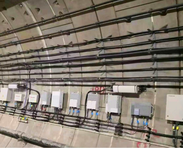
Metro Wi-Fi fails for predictable reasons, and almost none of them are about gain. A tunnel is a long metal waveguide with a bend in it, the passengers are moving at 60 km/h or more, and the only mounting surfaces are the tunnel wall and the platform ceiling. Adding dBi to a panel does not fix a bend, and it does not shorten a handover.
Work the arithmetic before choosing hardware. At 5.8GHz the free-space path loss is about 87.7 dB over 100 m and about 101.7 dB over 500 m. Free space is the optimistic case: in a tunnel the first tens of metres behave roughly that way, then reflections arrive and multipath either helps or eats the margin depending on geometry. The practical conclusion is that a 5GHz cell in a straight tunnel is useful out to a few hundred metres with a 15 dBi class antenna and a client at the train, and that anything longer needs more cells, a different band, or a leaky feeder.
Handover is the second piece of arithmetic. A 200 m cell approached at 60 km/h gives the train about 12 seconds inside the cell. That is a relaxed budget. The hard case is not speed but the moment the train passes a tunnel joint or a bend and the line of sight disappears faster than the association can move.
What we built for Hangzhou, and what it used
Our 5GHz reference installation is on Hangzhou's metro lines, where the deployment delivers 42 km of continuous 5GHz Wi-Fi coverage. The radiating element in that design is a dual polarized MIMO directional panel: 12 dBi across 2400-2500 MHz and 14 dBi across 5150-5850 MHz, a 50° horizontal / 60° vertical pattern on 2.4GHz narrowing to 45° / 40° on 5GHz, VSWR ≤ 1.8, 50 W of power handling, four N-Type Female ports, in a 239 × 190 × 35 mm, 1.2 kg outdoor housing.
Two features of that design are worth carrying into new projects. The dual-polarized feed is not decoration: two decorrelated streams at the same output power buy roughly 3 dB of link margin against a single-polarized client at the cell edge, and they do it without extra spectrum. And the 2.4GHz half of the antenna earns its place as a fallback rather than as a coverage layer, for the reasons set out below.
The three 5GHz antennas we now specify for track-side coverage
For the straight run: a 5GHz MIMO sector antenna. Our 90° dual-polarity sector covers 5150-5850 MHz at 15 dBi with a 90° horizontal and 8° vertical pattern, VSWR ≤ 1.8 and 100 W of power handling on two N-Type Female ports, in a 510 × 128 × 58 mm, 3.0 kg housing. Wall-mount it at head height along the tunnel and it produces a shallow, wide cell that follows the run instead of pointing across it. The 100 W rating matters when the same antenna has to sit a metre from a high-power access point.
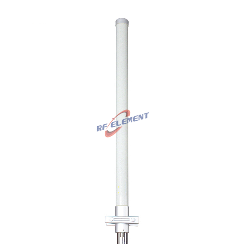
For platforms and tunnels with no suitable mounting face: a 5GHz MIMO omni antenna. The 12 dBi dual-polarity omni radiates 360° in azimuth with a 7° vertical beam across 5150-5850 MHz, VSWR ≤ 1.8, 50 W, two N-Type Female ports, in a Φ75 × 650 mm, 2.0 kg radome. Platform ceilings are usually flat, continuous and already cabled, which is exactly where an omni beats a sector on installation cost.
For station-to-station backhaul: a 5GHz parabolic dish. The 30 dBi dish covers 4900-6000 MHz in three sub-bands with 28 ±0.5 dBi at 4900-5150 MHz, 29 ±0.5 dBi at 5150-5850 MHz and 30 ±0.5 dBi at 5850-6000 MHz, a 5 ±0.5° beam, front-to-back ratio of ≥ 32 dB in the lower sub-bands and ≥ 30 dB above 5850 MHz, 100 W on two N-Type Female ports with a Φ600 mm reflector at 7 kg. It is a link antenna. Do not mount it over a platform and expect coverage.
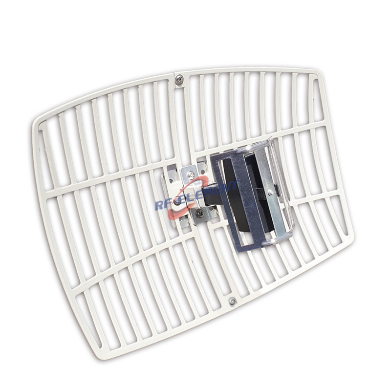
Where the corridor is wall-mounted rather than ceiling-mounted and the operator wants both bands on one part, the higher-gain dual band WiFi panel antenna covers 2400-2500 MHz at 16 ±1 dBi and 5150-5850 MHz at 18 ±1 dBi with a 30° / 25° horizontal and 18° / 16° vertical pattern, VSWR ≤ 1.8, 50 W and four N-Type Female ports in a 350 × 350 × 45 mm, 2.0 kg housing. Its 14 dBi sibling carries the same two bands with a wider 50° / 45° horizontal pattern for shorter, wider cells, and the 12 dBi dual band omni takes the same job on a pole where the wall is too cluttered for a panel.
Why one band alone is usually a mistake underground
5GHz needs line of sight. In a straight tunnel you have it. In a curved tunnel, a cutting, or a station box where the track is below the platform edge, you do not, and a 30 dBi dish pointed down a curve is wasted metal. The 2.4GHz half of a dual band part diffracts around those obstructions at the cost of bandwidth, which is the correct trade for passenger messaging, CCTV backhaul and ticketing traffic even when it is the wrong trade for video streaming.
That is why we specify dual band hardware for platform and corridor cells and reserve the narrow 5 GHz parts for the run itself. If the operator's spectrum plan forces DFS channels on 5 GHz, run the same layout with the 2.4GHz side as the control and handover path and treat 5 GHz as added capacity.
Where 5GHz is the wrong choice
Curved tunnels with no line of sight. Use a leaky feeder or radiating cable, or step down to 2.4 GHz. A higher-gain 5GHz antenna makes the link budget look better on paper and performs worse in the tunnel.
Coverage cells, not links. A 30 dBi dish has a 5° beam. Pointing one at a platform produces a single narrow spot and nothing else.
Very long runs on a single access point. Beyond a few hundred metres in a straight tunnel, splitting the run into cells with the 15 dBi sector costs less than one oversized antenna that cannot deliver the client count anyway.
Tunnels where the mounting height is below the loading gauge. A 510 × 128 × 58 mm sector needs a fixed face. If the only clearance is in the train's swept envelope, the answer is a ceiling omni on the platform, not a wall sector in the tunnel.
What to send us
Six items let us size the layout: tunnel cross-section and the tightest curve radius, the mounting face available and its height, the band plan and whether DFS channels are in use, train speed and stopping pattern, the target handover interval, and quantity per station. Where the run is long enough to need cells, we will also ask for the access-point model and its output power.
Prototypes of the parts above ship in three to five working days; volume orders take fifteen to twenty-five. Manufacturing sits in ZhaoQing, Guangdong, and OEM/ODM covers the mechanical interfaces a metro project usually has to negotiate: port orientation, cable exit, bracket and radome finish, plus a gain or beamwidth re-tune on the existing tooling when a tunnel needs a pattern we do not stock. Send the tunnel drawing and the band plan to sales@rfelement.com and we will come back with a cell layout and a part list.
TAG:The 5GHz WIFI Signal Coverage Solution for Metro Lines https://www.rfelement.com